This thread has been locked.

If you have a related question, please click the "Ask a related question" button in the top right corner. The newly created question will be automatically linked to this question.

LMR51606: The -15V output is failed for the LMR51606YDBVR

Part Number: LMR51606
Other Parts Discussed in Thread: LMP8640

Tool/software:

Dear,

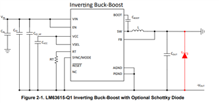
      We use LMR51606YDBVR per datasheet to build a +15V and a -15V output, now the board is in house, the +15V works ok,  but the -15V is failed to output? Would u like to take a look at our SCH as attached? Is anything wrong with the design? Thanks.

power.docx

  • Hi Liz,

    A few things are different from the buck to an inverting buck-boost converter.

    Basically, input caps will need to be reconnected to a new system ground, and a cap, CIO (represented by C209) needs to be connected from input to output to account for transients. 

    The enable will also need to be level shifted (or connected to VIN).

    Please see the attached app note:

    https://www.ti.com/lit/an/snvaa65/snvaa65.pdf?ts=1740766905941&ref_url=https%253A%252F%252Fwww.google.com%252F

    Thanks,

    Richard

  • Dear Richard,

    We changed the circuited as the attached file-15V ISSUE of LMR51606.docx:

    1. Add a 10uf Cap between 24V and GND.
    2. Short L15 and add 10uf between 24V and -15V.
    3. Short R303 and remove R304.

    And got the wave below, still not worked. The load of -15V actually is very light. Any other hints?

    “C1”  is the signal “-15V”.

    “C3” is the signal “pin 6:SW”of LMR51606.

    ‘’C4” is the signal “pin 4:EN”of LMR51606.

    Thanks,

    Liz

  • Hi Liz,

    It looks like something is pulling up the output. I see that you have a TVS D28, is it possible to replace it with a schottky rated higher than the absolute max of the 15V? 

    Were these capacitors derated for the increased input? Derating may make the passives have lower values than intended. 

    I would also suggest isolating the IBB from any other circuit to make sure there is nothing coupling in. 

    Thanks,

    Richard 

  • Dear Richard,

    We found that the current sense circuit of -15V power rail coupled with the FB resistor network. Disconnected the U31(LMP8640) and the -15V outputted normally. 

    So is there any good solution to sense the current of the -15V power rail but not coupled with the IBB? The rated current is less than 100mA. (detail see the attached file power.docx posted before) Would u like to recommend some IC for us to us? Thanks.

  • Hi Liz, 

    I think the method of sensing the inductor current is ok, but there may have been some interactions between the IC and current sense amplifier.

    Maybe another possibility is to sense the inductor current, if the ripple is small, but I think it may be best to ask the current sense amplifier team for a recommendation. 

    Thanks,

    Richard