This thread has been locked.

If you have a related question, please click the "Ask a related question" button in the top right corner. The newly created question will be automatically linked to this question.

UCC27712-Q1: Propagation delays measurement

Part Number: UCC27712-Q1
Other Parts Discussed in Thread: ISO5852S, UCC27712

Tool/software:

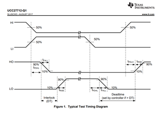
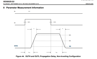
in the UCC27712-Q1 datasheet mentions below diagram for propagation delays measurement. for example tPDHL is measured from PWM 50% to HO  90%. similarly tPDLH is measured from PWM 50% to HO  10% .  where as in ISO5852s datasheet propagation delays are measured from PWM 50% to OUTH/L 50% (see the below screen shot from ISO5852s datasheet). why there is a difference .

  • Hello Naga,

    The most accurate way to measure propagation delay would be to have a fast rise and fall time on the driver inputs, to not affect the delay measurement and measure the time from the driver input to when the driver output starts the transition, rising or falling. Also in many driver prop delay measurements, the driver load is 0nF to not impact the measurement. Also on the ISO5852S the driver load is 1nF which means that you will see some of the driver rising and falling time as well as the signal propagation delay.

    The most common way to specify propgation delay is how the UCC27712 is specified. This way you do not see contribution (and variation) of the measurement based on the driver output rising and falling time. The driver rising and falling time is measured as its own parameter, and is dependent on the driver load and drive strength.

    I don't know why the ISO5852S was specified in that way but can just comment that the UCC27712 method is more common.

    Regards,