This thread has been locked.

If you have a related question, please click the "Ask a related question" button in the top right corner. The newly created question will be automatically linked to this question.

LM25149: Automotive Part more stable?

Part Number: LM25149

Tool/software:

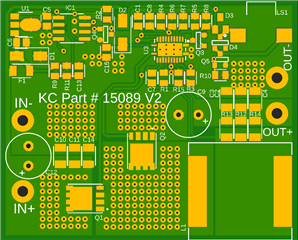
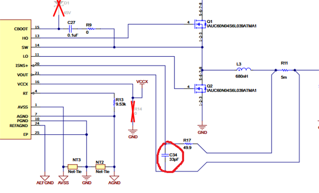
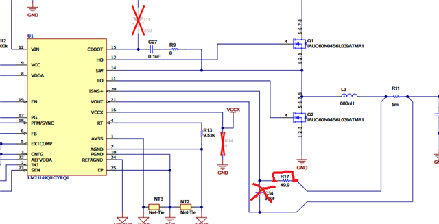
When I use the Automotive version (LM25149-Q1) then this design works well up to 11A, then the output voltage drops from 13V to 11V, and then it continues to power at 11V until 17A load, which is when it shuts down...

I made samples of this design 8 months ago with the Automotive part and they have tested perfectly and they still work perfectly now, they put out 13V at 16A and shut down at 17A... 
I then made 500 production boards with the non-automotive part and they are VERY unstable (lots of audible noise)... Changing to the automotive part makes them quit making noise, but then they have this strange 2V drop at 11A load...

What are the differences between the automotive part and the non-automotive part and why is the automotive stable and not the regular?

  • After more testing, I have found that it is much less noisy when I power from a battery (my application is battery powered) ...

    I also added a 7mOhm resistor in parallel with the 2 - 5mOhm resistors and now it is stable with the non-automotive part when between 13A and 15A load...
    Why does less than 13A make so much noise?

  • Hi Luke,

    I dug up so info on inductor whistling, and it's tied to the customer load profile and the COUT configuration (maybe they need some some lower ESR caps. They also may want to experiment with different inductors.

    This was my colleague, Ridge's conclusion at the end:

    We cannot offer specific recommendations on specific part numbers on capacitors. However, I was able to look in the lab and I think this issue is related to the customer load profile. With a stable load, the inductor or capacitor whine did not happen. With a load profile similar to the customer, there was audible noise. This is an issue with the load and the capacitors. Not the buck converter IC.

    This audible noise appears to be the result of the piezo-electric effect found in capacitors. How loud the ringing is can depend on the magnitude of the output voltage ripple during the transient, the type of capacitor used, the orientation of the capacitor, the size of the capacitor, and the frequency of the oscillation.

    The load may be changing at a frequency of ~10kHz, which is right in the middle of the audible range. The customer should try to stabilize their load.

    For the capacitors:

    • smaller physical sizes of capacitors will generate less noise
    • Capacitors oriented in the same direction can cause more noise. 90 degree offsets in the orientation of the capacitors could help.
    • X7R or better quality capacitors will help reduce this effect.

    Another way to help this issue could be to help reduce the output voltage ripple during the load transients. More output capacitance or increasing CFF could help to reduce this output voltage ripple. The less ripple you have, the less audible the noise should be.

    Thanks,

    Andrew

  • The load is completely stable, it is a resistive load center... 

    I added 12 Ceramics in parallel to the output with no difference in operation...

    I will try a CFF capacitor...

  • /cfs-file/__key/communityserver-discussions-components-files/196/Scope-Captures-SW.zip

    Capture 001-004 are this design with the LM25149-Q1 Part - 001 is no load, 002 is 5A load, 003 is 10A load, and 004 is 15A load.

    Notice how the duty cycle jumps down from 10A to 15A. This jump happens all at once and I need to get rid of this. Can you advise how to do it?

    At this point I think my only option is to switch out the 500pcs I have made to the Q1 part, as the regular part does not work at all. Is there any way to get a refund for these faulty parts?

    Capture 005 is no load, 006 is 5A load, 007 is 10A load, and 008 is 15A load on the regular part, the output voltage is not steady at any point, there is audible noise, and just nothing works...

    Do you agree that the Non-Q1 parts are faulty or why is there so much difference? My quick start calculator says it is for both models...

  • Hi Luke,

    I understand you're a bit frustrated, but it's a bit early to decide that the non-Q1 parts are faulty, there's quite a bit of noise on the -Q1 scopeshots you sent.

    Can you send the filled out calculator tool?

    How are the input capcacitor placed? Are they near the Q1 and Q2 MOSFETS?

    Also, I noticed that you have the 50Ohm Isns resistor, but you don't have a VOUT coupling capacitor. Does shorting out R15 reduce noise?

    Thanks,
    Andrew

  • I can't really tell if shorting R15 reduces noise or not, but it is definitely still noisy with R15 shorted...

    These boards were not very well layed out but I keep coming back to the fact that they work okay with the Q1 part...

    /cfs-file/__key/communityserver-discussions-components-files/196/LM25149-Quickstart-Calculator.xlsm

    I have no idea how to determine the ESR of my ceramics, the polymer electrolytics are 24mOhm...

  • "VOUT coupling capacitor"

    Where should this capacitor you mentioned be placed?

  • Hi Luke,

    This how the capacitor is used on the EVM:

    Thanks,

    Andrew

  • This capacitor definitely helps at some points...
    It is now stable at 0A, 3A, 5A, and 7A and above, but at 1-2A, 4A, and 6A loads the voltage randomly drops to 8V-11V output from 13V....

    I don't see any rhyme or reason for this issue...

  • I went from a 56pF to a 1nF to a 10nF to a 100nF decoupling capacitor and get some varied results, but one thing seems to be constant, that at 12A, whether it is stable or not, the output voltage drops down to 10.5-11V... I do not understand this... The 1nF capacitor seems to be the most stable, but it still does this...

  • Hi Luke,

    What effect does doing the opposite do?

    What happens if you remove the coupling capacitor and the short out the ISNS resistor. Could be not setting the current limit correctly. Can you share the inductor current, if possibe?

    Thanks,

    Andrew

  • I did this, and the audible noise is back, and also with 1A load, the output voltage is at 8V, with 2-12A load the output varies between 13V and 6V and it really jumps around... The 1nF capacitor is the perfect solution, besides we still need to get rid of the part where it jumps down to 10.5V... The duty cycle just jumps down like 10% and there is a hysteresis between the current draw when it jumps down and when it jumps back up... Is there any type of monitoring inside the chip that would cause this?

  • Hi Luke,

    When the device is current limiting and VOUT is being reduced, what's the voltage different between ISNS and VOUT? Is it not peaking at 60mV?

    Thanks,
    Andrew

  • /cfs-file/__key/communityserver-discussions-components-files/196/ISNS-VOUT-Voltage.zip

    See my scope images... 

    009 is with the scope across the current sense resistors with no load.

    010 is with a 10A load, output voltage still at 13V.

    011 is with 15A load, output voltage at 10.5V...

  • I have now adjusted this capacitor up to 5.6nF without making the circuit unstable and am now able to keep output voltages of 12.6V all the way up to 14A, but it still drops down to 11V output at 15A... I do notice that the spikes across the current sense resistors seem to double in frequency one the output voltage drops, does this mean it is the current limit?

  • Hi Luke,

    Yes, if there's a spike across the current sense resistor then the device will current limited. That's why the device is lowering the output voltage. My recommendation would be to try a larger Sense resistor and see if that fixes the problem.

    Thanks,
    Andrew

  • I had already tried this on day 1... I added another 5mOhm, so 3 in parallel, and it still has this voltage drop at the same load current...

  • I added the capacitor you mentioned and changed to a different switching MOSFET to eliminate this issue, which makes no sense to me but it works... Still I think there should be some indication that there is a difference in the automotive and the regular LM25149...