This thread has been locked.

If you have a related question, please click the "Ask a related question" button in the top right corner. The newly created question will be automatically linked to this question.

UCC28070: UCC28070 behaviour once the input is DC and not AC

Part Number: UCC28070

Tool/software:

Hi

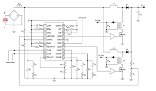
I am designing a high-voltage, 3-phase inverter with an interleaved Continuous Conduction Mode (CCM) PFC controller using the UCC28070 at the driver input. My goal is to make the design compatible with both AC (85 VAC to 265 VAC) and DC (120 VDC to 400 VDC) supply inputs.

If I apply a DC input at the AC input terminals before the bridge rectifier, what will happen to the UCC28070? Will it automatically disable itself, allowing the DC voltage to pass through the PFC inductor and diode directly to the DC link?


MM

  • Hello John , 

    The PFC stage is a non-isolated boost converter, which means that whenever the input voltage is lower than the output voltage, the controller will act to boost the input to a regulated output voltage.  Because it is non-isolated, any time the input voltage is higher than the output, that input voltage will pass directly through the inductor and output diode to the DC link capacitor in an uncontrolled manner.  

    That is what happens at initial power-up when the DC-link voltage is zero... there is inrush current that charges the DC-link capacitance to the peak of the input, whether AC or DC. 
    Normally, a bypass diode is added across the inductor and boost diode to divert this inrush current away from the inductor.  The bypass diode is not shown in the diagram above. 

    If your PFC output voltage is set for, say, 390Vdc which is suitable for 265Vac input, then 400Vdc input will pass through the inductors (or bypass diode) and over-charge your PFC output to 400V (ignoring diode drops).  If you intend to provide up to 400Vdc input, I recommend to design your PFC output regulation to at least 10V, preferably 15 V higher than the peak DC input.   That will avoid any over-voltaging and uncontrolled input current, and will work for the AC input range as well. 

    If Vin is allowed to be higher than Vout, then the UCC28070 will stop switching when Vin >/= Vout as measured at the VINAC and VSENSE inputs, but the detection may not be exact and there may still be switching going on when the inductor might become saturated from inrush current.  In that case, the PKLMT setting will limit the peak current, but the turn-off delays to the MOSFET finally stopping conduction may allow excessive peak currents through saturated inductors. The MOSFETs and other power components must withstand this. 
    I recommend to avoid this situation if you can help it.

    Aside from the above, teh UCC28070 relies on detecting zero-crossings at the VINAC input to determine if the AC input peaks are reducing (RMS is going lower).  Rising RMS (and rising AC peaks) are easy to detect almost immediately, but falling peaks must be compared to the previous line-cycle's peak to determine if the RMS is going lower and a higher gain is needed for the multiplier.  DC input does not have zero-crossings, so rising DC can be detected, but falling DC cannot be detected without zero-crossings.  

    To solve this, "artificial zero-crossings" must be injected into the VINAC signal periodically to mimic the rectified AC-line behavior.    
    Please see this previous E2E on that topic: 
    https://e2e.ti.com/support/logic-group/logic/f/logic-forum/1459127/ucc28070-ucc28070-for-dc-input-pfc-application?tisearch=e2e-sitesearch&keymatch=UCC28070%20DC%20input# 

    Regards,
    Ulrich

  • John,

    To further clarify, if you plan to bypass the PFC feature with DC bias, I suggest you to add a bypass switch instead of relying on the inductor to carry the current. Otherwise, the inductor will limit the current when you have a transient load. 

    Ning