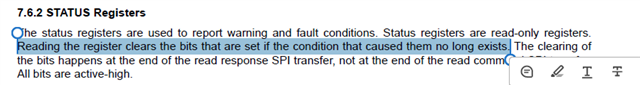
This thread has been locked.

If you have a related question, please click the "Ask a related question" button in the top right corner. The newly created question will be automatically linked to this question.

TPS92520-Q1: TPS92520 Open Circuit Diagnosis Strategy

Part Number: TPS92520-Q1


Tool/software:

Hello, Experts.

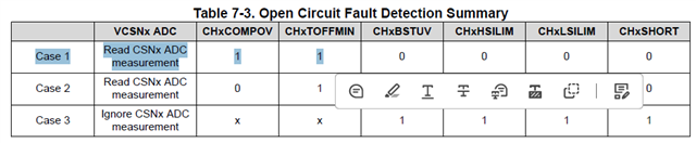
We tested the open circuit test of TPS92520 and found that sometimes the open circuit fault cannot be reported.

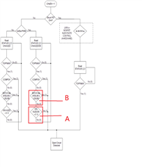
We have already done it according to this detection logic, and there is still a certain probability that the fault cannot be reported, the waveform of the output voltage of our test 92520 is as follows, and the waveform is close to the STATUS 3.

However, in the test, it is found that the condition of point B cannot be established, and the condition of point A may not be established.

Please help us to see how we should improve our logic of detecting open circuit, or which part is wrong, thank you

  • Hi, Lin, 

    What configuration when you are doing open detection? Is there any int/ext. PWM dimming or shunt dimming? Do you keep open status all the time during the test or go back to normal operation after open test? 

    Also, can you help polling register data including STATUS1, STATUS2, and STATUS3?    

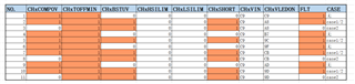
  •  Hello, this is the register change after we monitor the output of tps92520. It seems that there will be situations other than CASE1/2/3. Please help me to look at it again.

  • Can you check questions listed in first  chapter above? Can you share the schematic as well?

    If you are using external PWM,pls also capture UDIM together with VOUT.

     How you test  and record case 1to11?Pls share the details. It might be possible that some faults been cleared after last read.

    You may use logic analyzer to capture SPI data together with Vout (use analog input , pls use voltage divider like 1M+100k to attenuate output voltage to low voltage that acceptable for logic analyzer. )

  • No external matrix chip is used, and the internal PWM of TPS92520 is used for dimming, with a frequency of 215Hz.

    Test method: After disconnecting the load, monitor the signals listed above;During this period, the LED load has been disconnected, and then the above register data is collected.

  • For No. 1, 4, 6, 9, Open circuit is also detected. Please refer to below case 1. 

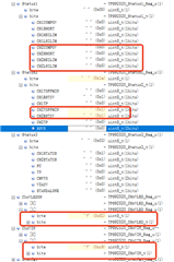
  •  This is the case where we tested the open circuit. This picture is the register state diagram, but CASE1/2/3 did not appear at the same time.

  • You don't need case 1/2/3 appearing at the same time. Either one meets the table, open status is detected. 

  • Yes, I understand what you said. If we perform open circuit detection according to the above flowchart, there will be a probability that CASE1, CASE2 or CASE3 will not be satisfied, I attach this picture to illustrate the scene that does not meet any CASE when there is an open circuit.

    I would like to add the detection strategy on our software, only after meeting the above flow chart conditions for 10 times in a row will the open circuit be reported. If there is a normal time during the period, it will not be reported. Therefore, if we have an open circuit, we will report a fault for a while, no fault will be reported later.

    Is there any other detection logic for us to refer to, thank you.

  • What is the result when you first read register data after open condition? What is the delay time for each reading? Can you read with longer delay time? 

    some registers fault might be cleared if you repeatedly read status registers as "Reading the register clears the bits that are set if the condition that caused them no long exists."  You may read result with waiting for long enough time.