This thread has been locked.

If you have a related question, please click the "Ask a related question" button in the top right corner. The newly created question will be automatically linked to this question.

LM5148: Circuit not able to deal with 24V@25A

Part Number: LM5148
Other Parts Discussed in Thread: LM5137, LM5143

Tool/software:

Hi,

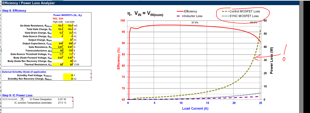
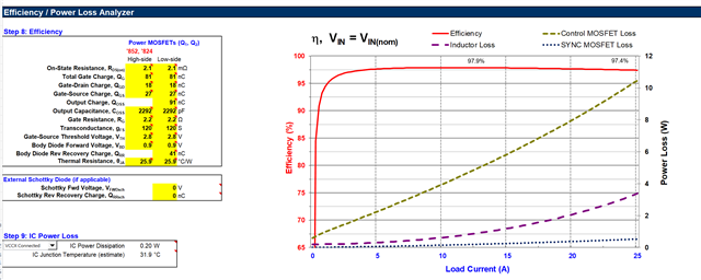
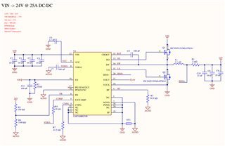
I designed a DCDC regulator for supplying 24V at 25A, by using the calculations from the Excel file and the layout guidelines from the LM5148 datasheet and the Evaluation board.

The schematics are shown in the picture below.

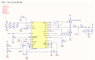
The problem I'm facing is that it seems that the circuit is not able to deal with more than 15A, even though everything is rated to be able to deal with the desired level of voltage and current. Attached you can fin the BOM.24V_25A_Power.xlsx

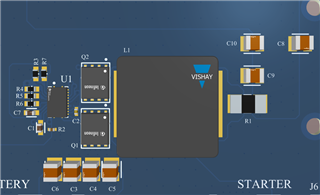
During a test, at 20A the high-side MOSFET (Q1) blew and during another test I stopped it at 15A because some components were too warm (by checking with an IR camera), specially the resistors and capacitors in the left side of the LM5148 (U1), not sure that the polygon for AGND is too small.

Could anybody please, help me with this, I don't know what is the issue for this lack of performance and thermal issues. Could you please confirm that the LM5148 is able to provide 24V@25A at its output?

Thanks in advance.

  • This is the PDF with the layout.
    24V_25A_Power.PDF

  • Hello Angel,

    running at 25A will require thermal mittigation, the losses are likely too high without addtional cooling methods to mitigate temp rise.  have you tried running the prororype with a cooling fan to narrow down the reason for failiure?  

    Can you share your calculator spreadsheet you used to design this?  Thanks.

    David.

  • Thanks for your answer.

    LM5148_LM25148_24V_25A.xlsm Here you have the calculator.

    A fan is not an option I'm afraid.... I was looking at some MOSFET with the same footprint to replace the MOSFET that I already have.

    These MOSFET are able to deal with a higher level of current, what do you think?

    Infineon_IAUCN10S7N021_DataSheet_v01_10_EN-3445924.pdf

    Datasheet ISC046N13NM6

    Infineon_ISC055N15NM6_DataSheet_v02_00_EN-3478170.pdf

  • Hello Angel,

    It's not about the Id current rating, but the loses in the MOSFET.  Please fill out the MOSFET parameters, in the calc spreadsheet and check the losses.  You cannot dissipate more than a few watts in each FET otherwise will overheat in high temp environments.   from experience, switching at 700kHz will incur much higher losses than switching at say 200kHz. However, see below your entries, does not look right.

    Hope this helps.

    David.

  • Thanks for your help David, I was not taking this into account.

    What is an acceptable level of power dissipated by the MOSFET? I found some MOSFET able to deal with more than 100W of dissipated power.

    I found this MOSFET Datasheet BSC034N10LS5 which is able to deal with up to 156W. I add it data in the calculation Excel.

    By other hand, I redo the calculations for a lower switching frequency as you suggested, but using components with the same footprint as the one they are going to replace, as I want to rework the boards and test them based on the new calculations. 

    This is the Excel with this new calculations. LM5148_LM25148_24V_25A_BSC034N10LS5.xlsm

    What do you think about it? Could it be work to reach the 25A?

    Thanks for your help and support.

  • Hello Angel,

    The power dissipation spec is a more of a pulse power specification.  However, the way we select a suitable MOSFET for a switching regulator is take the power dissipation and multiply it by the theta JA.  Thats the thermal resistance between the Junction and Ambient (RJA).  With this in mind, if we dissipate 3W and its RJA is say 25C/W this FET would rise 3W*25C/W = 75C above Ambient.  If your max ambient is 85C, then your Junction Temp will be at 85C+75C = 160C.  In my opinion, this will be too high, you want to keep the Temp <150C or so.

    This is the limitation you have to work with, not the Pd of the Device, or the ID Current.  

    Suggest you parallel the FETs to share the losses and spread heat.

    Also please note this device has a gate drive voltage of 5V and logic level FETs will need to be selected.  The FETs you have listed above are not suitable.  you need a miller plateau voltage of about 3V so you have enough voltage reserve to charge the capacitance between Gate and drain which reduces switching transition times and allows for less losses. 

    Hope this helps,

    David.

  • Thank you very much David, your help is ultra useful. Now I realise that I'm not taking into account all this characteristics.

    Let me take a look at it an I would like to check with you whether is feasible or not.

    Again, thanks a lot for your help.

  • Anytime Angel,

    Looking forward to your response.

    David

  • Another question that comes to my mind is: is this chip (LM5148) the best option for what I want to implement?

  • Hi David,

    By reducing the switching frequency to 250KHz (if I decrease more the power loss in the inductor is much higher), and selecting another MOSFET with a better thermal resistor and low Rds (Infineon_IAUCN10S7N021_DataSheet_v01_10_EN-3445924.pdf), I reduced the power loss in the MOSFETs.

    LM5148_LM25148_24V_25A_IAUCN10S7N021.xlsm

    But it's still to much knowing that at 25A the power loss in the MOSFETs is 10W, so 10W*25.9C/W=259C!! Even paralleling 3 MOSFETs is just to much.....

    So my doubt is, is it feasible to achieve 24V@25A with the LM5148, or should I select another DCDC from TI's portfolio? I can't find a MOSFET with a better thermal behavior and I don't know what can I do to reduce the power loss in the MOSFETs.

    Do you have any suggestions?

    Thank you in advance.

    Ángel

  • Hello Angel,

    I agree with your findiings, as I alluded to earler, acheiving 25A without air cooling or agressive thermal management is going to be really a challagne.  please consider the LM5137, or the LM5143, these are dual phase controllers that can be configured as a ssingal output dual phase.  Hope this helps.

    David.

  • Hi David,

    Finally I found some MOSFET with a low Rds and a pretty good thermal behavior so with a switching frequency of 250KHz and replacing the inductor by a 6.8uH one, I got this calculations:LM5148_LM25148_24V_25A_BSC010N04LS6ATMA1.xlsm
    I'm supplying the circuit with a 7S LiPo battery and I'm able to reach 20A with a very good thermal behavior for the MOSFETs and the inductor, but I cannot reach more current than that as if I increase the current consumption (I'm using 2 300W electronics loads) the output of the DCDC (voltage and current) drops suddenly. It seems that everything is alive and not I don't think is an thermal issue because as soon as I turn off one of the loads, the output goes at normal state in the other load (24V@10A). 

    Regarding the thermal behavior the circuit works fine for more than 30 minutes at 20A with not current drops.

    I know that for 200Khz the coil is a bit smaller than it should (I'm modifying the boards that I have for testing), so I increased the switching frequency to 320Khz but the behavior is basically the same (I think I can reach a higher output current but not very significant).LM5148_LM25148_24V_25A_BSC010N04LS6ATMA1_320KHz.xlsm


    Is this problem caused by the coil which is not enough to provide the 25A? The coil I'm using now is rated at 26A max and 36A current saturation. Would the external compensation improve the behavior of the circuit?

    Thanks in advance for your help.

    Kind regards.

  • Additionally, during the tests, I kept the 3.3uH inductor with the 200KHz-switching frequency and the circuit was able to provide only up to 13A, so when the loads were demanding more current, the output was 13A, no more than that, but without any drop. So if the issue is the coil not big enough I would expected a similar behavior instead of dropping the output. 

  • Hello Angel,

    In the above tests, what is the inductance value you are using?  what is the switching frequency?  What is your Rsense value?

    please share the scematic you are currently testing, with the latest sprewadsheet with those values inserted therein.

    Thanks.

    David.

  • Hi David,

    Attached in the previous post you can find the Excel with the calculations for 250Khz (200KHz was incorrect) and 320KHz. In both cases I was using a 6.8uH inductor.

    The schematic is the same but modifying the components for testing.

    Thanks for your answer.

  • Hello Angle,

    I am unable to zoom into this image for some reason can you upload the schematic and detail what you are testing, still not clear from your description above...

    Thanks.

    David.

  • Oh I'm sorry.

    This is the original circuit based on the LM5148:

    As the original circuit was not able to deal with the power load, following your suggestion I reduced the switching frequency to 250KHz. For this, I replaced the RT resistor (R3), the inductor by a 6.8uH one (XAL1510-682 | Molded Inductor | Coilcraft) and the MOSFETs for another part number with lower Rds (Datasheet BSC010N04LS6). I added as well, 42uF in the output.

    With these modifications, the circuit reaches 24V up to 20A in the output, being supplied from a 7S-LiPo battery and having 2x 300W-electronic loads. The thermal behavior is pretty good and the circuit is working fine until the test finished (30 minutes). The issue is if the loads demand more than 20-21A, the output drops and the circuit stops providing the 24V and the current, but as soon as I turn off one of the loads the output is back to normal (24V at 10A demanded by the load that is still on).

    The calculations for this scenario are in this Excel file: LM5148_LM25148_24V_25A_250KHz.xlsm

    After this, I modified the RT (R3) for having 320KHz (keeping the same MOSFETs and 6.8uH inductor) and check if the circuit is able to provide more current than at 250KHz, but the result is the same or al least, not a big difference. The calculations for this setup are in this Excel file: LM5148_LM25148_24V_25A_320KHz.xlsm

    Then, I thought that probably, the issue is due to the inductor not being able to provide more current because it is too small, so I took another board, carried out with the same modifications (MOSFETs, RT (250KHz) and output capacitors (+42uF)) but keeping the original coil (3.3uH). The result for this test is that the circuit is only able to provide 24V at 13-14A but if the loads demand more current, the circuit keeps its maximum current (13-14A) but it doesn't drop as it happens with the others setups.

    Do you know what could be the cause that makes the circuit to drop with more than 20-21A? Would the external compensation improve the behavior of the circuit? I seems that something "saturates" when the demand is more than 20-21A, maybe there is something in the Bode diagram that I'm missing....

    Thanks for your help, I don't know if the issue is clear now, otherwise, please let me know. 

  • Thanks Angel,

    Appreciate you surmising the steps in one response, that was very helpfult to me.  I dont think going to another board with an even lower Lbuck is advisable, its important to stick with the ball park recomendation of the spreadsheet.  I think you might be hitting current limit.  Try reducing Rsense from the 2mR to 1.5mR and report back if you can now get more current out of the supply.

    Thanks.  David.

  • Hi David,

    Decreasing Rsense solved the issue (I placed 2x 2mR in parallel for testing) and now I reached the target of 24V at 25A.

    After all the tests and calculations with the MOSFETs, inductors and switching frequencies, I was focus on that topics and I didn't take into account Rsense (I thought that 2mR was enough with margin, because from the calculations 2.3mR was the maximum).

    Thank you very much for your help during all this process, I really appreciate it.

    Kind regards.

    Ángel