Other Parts Discussed in Thread: PMP6812, TPS23754
Tool/software:
Hi Sir,
According to previous TPS23754-1(TPS23754PWPR-1) WAPAX09 project POE issue we raised by another thread, we create this new thread to discuss more questions.
Based on WAPAX09 TPS23754-1 schematic and TI PMP6812 schematic, you had provided the Cap calculation formula shown below.
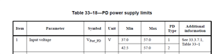
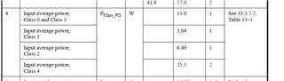
Using I=Cdv/dt with I=25.5W/42.5V=0.6A, dv=42.5-36=6.5V and dt=250usec results in C=~23.1uF
Power Bulk Cap
13W 10-22uF
25W 33-47uF
50W 68-100uF
70W 100uF-200uF
25.5W 推薦33-47 uF. 22uF 比較worst的250us 0-current transient不行,但99.9%的情况影響不大
From your reply and 145.3.8.6 PD behavior during transient at the PSE PI information, we have some questions.
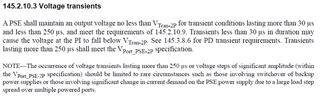
1.It shows PSE PI has to maintainan output voltage and the voltage transient longer than 30us and less than 250us to PD.
As you said above, 22uF cap is not appropriate for voltage transient that is 250us condition.So, you suggest 33-47 uF for 25.5W.
Is it correct?
2. As you said above,what is the meaning of this 但99.9%的情况影響不大? Did you mean 22uF can meet 250us 0-current voltage transient?
Is it correct?
3. If 22uF is appropriate for 250us 0-current voltage transient, why TI suggest 33-47 uF? We are confused.
Please help to explain more information for us to realize.
4.How can we measure the 250us 0-current voltage transient? Is it at detection procedure?
Can we avoid 250us 0-current voltage transient happened?
5. As you mentioned, If the PD cannot pass the handshake, can you double check all caps between VDD-VSS is less than 120nF?
How can we check all caps value? It is calculate by schematic or how can we check the 120nF? Please provide the guideance and method.
6. As you mentioned, If the PD is connected then power off, it may be related to the loss of maintain power signature. Could you try with a load > 1W?
Where we have to add a load >1W? please based on attached WAP-AX09 schematic to provide the guideance how to implement.
thanks
TPS23754-1_PSE voltage transient to PD question20250304.pptx