This thread has been locked.

If you have a related question, please click the "Ask a related question" button in the top right corner. The newly created question will be automatically linked to this question.

TPS65987D: How can I set the TPS65987D to turn on PPHV only when a PD adapter is detected?

Part Number: TPS65987D
Other Parts Discussed in Thread: BQ25723, TPS65987, BQSTUDIO, EV2400

Tool/software:

Hi all,

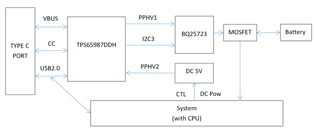
We used the design scheme of TPS65987D+BQ25723 and the charging function is tested normally.

Now we have a problem, our board power consumption is close to 15W, and when connecting to a PC host via USB with the battery connected, there will be a host prompting for a USB power surge.

So we wanted to leave PPHV1 unconnected when we plugged into the PC host, which would allow the battery to power the system, thus avoiding USB power surges on the host.

That is, we want to turn on PPHV1 only when the TPS65987D negotiates the PD protocol.

I hope you can tell me how to realize the above requirements.

Appreciate it!

Xavier.

  • Hi Xavier,

    I don't think I understand the ask, some of the descriptions are a little unclear.

    Let me outline what I understand and ask more clarifying questions:

    Understanding:

    • Current Board System power consumption is 15-W
    • Power is coming from Battery?
    • If a PC is connected to the USB-C PD port, the USB-C Port will become Source and the PC will prompt power, creating a power surge

    So you desire that when the PC is connected, we do not close the Source power path to prevent the source from drawing power?

    If this is the case, then no, we cannot support this as it is not legal from a USB-C PD perspective. What you are essentially asking is that we advertise and negotiate a contract and then refuse to actually supply the power.

    If you know you are in a state where you cannot source power from the port, you may be better off disabling sourcing during this time. With an I2C host, you can program Port Control to disable swaps to source (Process and Initiate), and then program the type-C state machine in Port Config to be sink only. When writing to the Port Config register, the PD controller will automatically renegotiate a contract with the new settings.


    So we wanted to leave PPHV1 unconnected when we plugged into the PC host, which would allow the battery to power the system, thus avoiding USB power surges on the host.

    This is a little confusing. Is the host drawing power or sourcing power here?

    That is, we want to turn on PPHV1 only when the TPS65987D negotiates the PD protocol.

    When the PD controller is negotiating with the PC host, it is very likely over PD protocol, I'm not too sure what you mean here.

    Thanks and Regards,

    Chris

  • Hi Chris,

    Thanks for the reply.

    • Current Board System power consumption is 15-W
    • Power is coming from Battery?

    You understand me fine.

    • If a PC is connected to the USB-C PD port, the USB-C Port will become Source and the PC will prompt power, creating a power surge

    The PC here is a desktop computer that connects its USB-A port to the USB-C port on my board via a USB A-C cable.  My board becomes a Sink device at this point, and the PC is the source and host.

    Before plugging into the PC, my board gets power from the battery. After plugging into a PC, the board changes the power path and prioritizes getting power from USB-C, which means it prioritizes getting power from the PC.

    As you know, the PC's USB-A ports usually don't provide a lot of current. So after connecting my board, the PC prompts for a USB port power surge.

    So I would like to know how to keep the PPHV1 still disconnected when I connect my PC. This means that the PC will not be powering the BQ25723 on my board and the board will still be powered by the battery.

    This is a little confusing. Is the host drawing power or sourcing power here?

    PC host is sourcing power here.

    When the PD controller is negotiating with the PC host, it is very likely over PD protocol, I'm not too sure what you mean here.

    The PC host we use is a USB-A port, which does not support the PD protocol. What I mean is that the TPS65987D will turn on PPHV1 to power my board and charge the battery only if my board is connected to a charger that supports the PD protocol.

    Thanks and Regards,

    Xavier.

  • Hi Xavier,

    Can you confirm which device and GUI you are using? (TPS65987D? H/K , 6.1.4?)

    Can you share the .pjt file you are using?

    How are you controlling the BQ25723? How/when does it charge vs. supply power?

    Can you provide a simple block diagram of your system showing the battery, system power rail, and type-c related blocks?

    I don't know of a way for the TPS65987, by itself, to specifically disable the sink path on USB-C default contracts. You would need an external I2C host in order to implement something that does this.

    Typically you would configure the Power Path used to be "Wait for SRDY" in the "Global System Configuration" register. What this does, is when the part is sinking power, it will not close the sink power path until an "SRDY" 4CC command is sent from an I2C host. You would need to set up the interrupts for "New contract as Consumer" and maybe "Plug Event" to indicate to a host that it needs to check the PD controller and potentially send an "SRDY".

    If you are using the I2C controller events table to control the BQ25723, there may be other options, but I'm not sure if they would work and would need to see your current pjt before making any decisions.

    Thanks and Regards,

    Chris

  • Hi Chris,

    Sorry to keep you waiting for a long time.

    Can you confirm which device and GUI you are using? (TPS65987D? H/K , 6.1.4?)

    The device I use is TPS65987DDH and the GUI tool version is 6.1.4 


    Can you share the .pjt file you are using?

    PD25030708.pjt

    This my .pjt file.


    How are you controlling the BQ25723? How/when does it charge vs. supply power?

    Can you provide a simple block diagram of your system showing the battery, system power rail, and type-c related blocks?

    I use the TPS65987D I2C3 connection to the BQ25723 for control.My board is designed to be an OTG device, which will supply 5V to the outside when it is a master device, and an external power supply to the board when it is a slave device.

    Here's a sketch of my board


    If you are using the I2C controller events table to control the BQ25723, there may be other options, but I'm not sure if they would work and would need to see your current pjt before making any decisions.

    I do use I2C controller events table to control the BQ25723,recently in my testing I found again that the BQ25723's Dynamic Power Management (DPM) function can meet my requirements,it is also a register that can be written to.

    The DPM register address is 0B/0A and the picture is its description.

    I set DPM register value to 0540, which means limiting the input low limit to 4.544V. Here's my process for doing that, when I plugged my board into the PC, I used the EV2400 to write 0540 for this register on the BQStudio and found that the PC would not prompt for a surge, and the PC's USB voltage didn't dip below 4.544V, meaning that the modification to the DPM worked.

    However, when I tried to write this register via the TPS65987D, I set up some I2C control events, and was not able to write to this register after connecting to the PC (i.e., 5V power supply without Sink PDO Negotiated), except for setting up the I2C control event to Sink PDO4 Negotiated, which allowed me to write this register successfully.

    It looks like this register is reset when the BQ25723 is connected to VBUS.

    Maybe you can figure out how to write a value to the DPM's registers using I2C's control events after plugging in a 5V VBUS without Sink PDO Negotiated.

    Also, I was trying to use the I2C control event 'PP k Switch On' as a DPM write condition, but it didn't work.Because all the 'PP k Switch On' in my pit file shows 'PP k Switch On (Closed)', I don't understand if it's because of this 'Closed' is the reason why I can't successfully write to the DPM registers.

    Thanks and Regards,

    Xavier.

  • Hi Xavier,

    I set DPM register value to 0540, which means limiting the input low limit to 4.544V. Here's my process for doing that, when I plugged my board into the PC, I used the EV2400 to write 0540 for this register on the BQStudio and found that the PC would not prompt for a surge, and the PC's USB voltage didn't dip below 4.544V, meaning that the modification to the DPM worked.

    Nice! This sounds like it works well

    Maybe you can figure out how to write a value to the DPM's registers using I2C's control events after plugging in a 5V VBUS without Sink PDO Negotiated.

    Unfortunately this might just be trying and testing different events to try the best one. You said that it potentially resets every time VBUS is provided?

    If this value only affect the sinking and you are fine with it being enabled the entire time, you may want to consider using the "Cable attach CC_1/2 PD" to program this register upon any connection (sink and source).

    Also, I was trying to use the I2C control event 'PP k Switch On' as a DPM write condition, but it didn't work.Because all the 'PP k Switch On' in my pit file shows 'PP k Switch On (Closed)', I don't understand if it's because of this 'Closed' is the reason why I can't successfully write to the DPM registers.

    I'm assuming here that it means the switch is "closed" in the on state. I have seen this event used too often, but it seems like it triggers when the Power path in mention is used.

    Thanks and Regards,

    Chris

  • Hi Chris,

    Thank you for your reply.


    Unfortunately this might just be trying and testing different events to try the best one. You said that it potentially resets every time VBUS is provided?

    If this value only affect the sinking and you are fine with it being enabled the entire time, you may want to consider using the "Cable attach CC_1/2 PD" to program this register upon any connection (sink and source).

    I have tested almost all I2C events, including “Cable attach CC_1/2 PD”, and none of them are able to write to the VINDPM register at VBUS=5V.

    In my testing, I found that the BQ25723 writes the default value “VBUS-1.28V” to the VINDPM register once after receiving the power input, which is bound to happen.


    I'm assuming here that it means the switch is "closed" in the on state. I have seen this event used too often, but it seems like it triggers when the Power path in mention is used.

    Thanks for the explanation. It sounds like it meets my trigger needs, but it really didn't take effect when tested, which puzzled me .


    I've been thinking about this for a long time again today and saw that the TPS65987D supports high/low level input triggering of GPIO.When BQ25723 receives VBUS, there will be a specific “low→high” level change, I think this level change can be connected to the IO, after the TPS65987D receives this change, it can write the value of the VINDPM register for the BQ25723 via I2C.

    In practice, I'm not sure how to go about configuring the i2c write operation after the GPIO receives a level change. Can you tell me? Or TPS6597D can't support this operation .

    Thanks and Regards,

    Xavier.

  • Hi Xavier,

    Let me review this and get back to you later in the week. I'm not too sure if we have a GPIO triggered I2C write. If none of the I2C events work, I'm not sure what alternatives there are here.

    Thanks and Regards,

    Chris

  • Hi Xavier,

    saw that the TPS65987D supports high/low level input triggering of GPIO.

    Where did you see this?

    I have been looking through the documentation we have and can not find any "GPIO Triggered I2C writes" unfortunately.


    I'm looking into another option for "disabling sink" and will update you next week.

    Thanks and Regards,

    Chris

  • Hi Chris,

    Where did you see this?

    I have been looking through the documentation we have and can not find any "GPIO Triggered I2C writes" unfortunately.

    I found out from Document: SLVAE11 that I can set the GPIO Trigger.So I'm asking if it's possible to “GPIO Triggered I2C writes”.I wasn't sure about this until then, and this seems to have caused you a misunderstanding, sorry .


    I'm looking into another option for "disabling sink" and will update you next week.

    That's great news, looking forward to your reply.


    One other thing, I can't see the TPS65987DDH page anymore, is it about to be discontinued? Is there a new product coming out?

    Thanks and Regards,

    Xavier.

  • Hi Xavier,

    Thanks for the clarification, I looked over the document. The "triggering" mainly relates to specific behaviors within the system and PD controller. Unfortunately I don't see anything regarding GPIO triggering I2C within the document and when checking with the team.

    After looking into some more of the GPIOs, there may be something you can try but it will require some effort on your end to modify HW and verify the fix. I don't currently have the tools to test this properly.

    Please see the attached document, there may be some typos, but the general concepts should be correct. You should test the three GPIO separately to verfiy their behavior. In particular, the last one(input) may need some verification. Realize this will prevent all Type-C Default sink contracts from delivering power to the system side of your design.

    TPS65987 Virtual config for Sink enable.pdf

    Thanks and Regards,

    Chris

  • Hi Chris,

    Thanks for the method, it does control the switch on the TPS96587D.

    But now there are some problems there with the BQ25723, when my system is working with a low battery, after plugging into the power supply for a few minutes to charge, unplugging the power supply, the system will instantly power down completely, then the battery re-attempts to re-supply the power fails and goes into a protection state.

    I think it's time for me to discuss this in the BQ25723 forum.


    One other thing, I noticed that the TPS65987D has now changed to 'Not Recommended for New Designs',

    1.How long will it still be guaranteed regular availability?

    2.Will there be any other new PD controllers supporting the 'DP Alt Mode' feature released recently?

    Thanks and Regards,

    Xavier.

  • Hi Xavier,

    But now there are some problems there with the BQ25723, when my system is working with a low battery, after plugging into the power supply for a few minutes to charge, unplugging the power supply, the system will instantly power down completely, then the battery re-attempts to re-supply the power fails and goes into a protection state.

    That might be related to the PD if you are using I2C events, could you get an I2C log between the PD controller and BQ device during this event and share it?

    Did you configure any I2C writes on unplug events that could be disabling the BQ device? Make sure no weird configuration occurs during this time

    1.How long will it still be guaranteed regular availability?

    The part is being EOL's not NRND'd. We don't currently have plans on EOL-ing the device, there just won't be significant support for new features and this part will not be updated to the latest USB-C PD compliance if compliance is something you need.

    2.Will there be any other new PD controllers supporting the 'DP Alt Mode' feature released recently?

    Unfortunately we currently do not have a direct replacement for DP alt mode PD controllers yet.

    Thanks and Regards,

    Chris