


Tool/software:
Dears,
The customer is currently using TPS54335 in a machine vision camera project. Recently, two cameras burned out. When the customer checked the problem, he found that the current circuit could not pass the simulation.
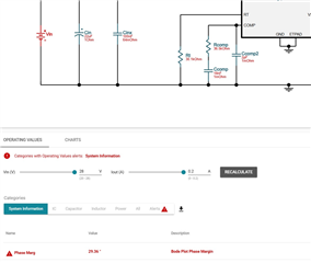
1. The customer calculated the compensation circuit according to the formula in the manual. Is the simulation inaccurate?
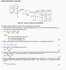
2. According to the formula, the value of R4 is only related to the switching frequency of 1.5MHz, the output voltage of 15V, and the output capacitance of 22μF. The calculated value is 37.4K. However, the simulated value is only about 15K. Why is this?
Below is the schematic:
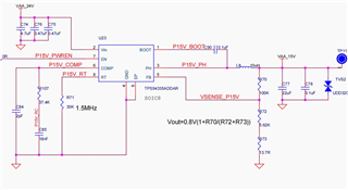
Please help analyze the reasons, thank you very much!

