This thread has been locked.

If you have a related question, please click the "Ask a related question" button in the top right corner. The newly created question will be automatically linked to this question.

LM5575-Q1: High current draw over the Diode in Idle. high idle current for negative -12V supply

Part Number: LM5575-Q1
Other Parts Discussed in Thread: INA181

Tool/software:

Hello,

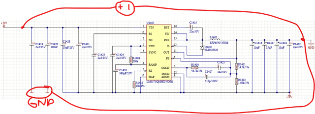
I am running into an issue with the LM5575-Q1 design below as an inverter.

its based 100% out of an webbench design.

according to webbench phase margin and all other parameters should be OK.

But when i power it on, i get around 500mA of current draw on the +12V supply with 0 load attached to the -12V side.

I measure around -1V generated.

without any power connected i measure around 500 Ohm between GND and -12V on the load side.
(the converter is on a board where other components are connect as a -12V load, so its not only the internal resistance of the converter)

I did check the webbnech design, but did not see any error.

can you help me identify why there is so much current loss.?

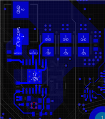
here is also a screeshot of the PCB design.

+12V input is at the bottom at the red circle.

so C1428 and C1421 are close to the input pin and input caps.

COMP and feedback circuit is on the other side of the board.

  • Hi Fabian,

    The schematic looks correct to me. Try removing each of the input capacitors (C1421 and C1428) one by one to see if they are leaky. Since the input to output voltage is almost 25V, I would suggest using higher rated capacitors 50V/100V. How is the input voltage being applied to the part? It is possible that the part was damaged when VIN was applied to the part because if VIN is slewed very fast, the capacitor voltage divider between VIN to -VOUT to GND will become positive. When -VOUT becomes positive in voltage, the internal diodes in the the IC will conduct current and potentially damaging the IC. See link below for more info:

    https://www.ti.com/lit/an/slva469d/slva469d.pdf

    Ben   

  • Thank You. I will try that. When i am back in the lab.
    The power is Coming from a hameg lab power supply. 

    what i should have mentioned. The Component that gets hot is the external Diode.  
    i checked polarity and it’s correct.  

    so i assumed the IC is doing something to generate that Flow through the diode?

    if i Reverse the diode i only have 5mA current draw but it does not generate a negative voltage either.

  • Hi Fabian,

    The diode in the schematic (D1403) is needed because the part is an asynchronous buck converter. Make sure when you connect the lab power supply that the positive terminal goes to VIN on the board and negative terminal goes to GND on the board. See below:

    If D1403 is getting hot, it seems that one of the input capacitors connected from VIN to -VOUT has broken down and is shorting VIN to -VOUT. See below:

    Ben

  • Hello,

    we found an issue with the inductor, which seems to a labeling issue.

    if thats true we run at a wrong impedance, will retest next week and provide an update.

  • Hi Fabian,

    Please keep me posted. Glad that you found an issue with the inductor.

    Ben

  • Hi Fabian,

    Are there any updates?

    Ben

  • hello

    i should get the new inductors today. then i will give you an update

  • Hi Fabian,

    Thank you for the update.

    Ben

  • Hi Fabian,

    Just following up with you if you have any updates. If not, please close the thread by clicking on "resolved". Thanks!

    Ben

  • hello

    i am still working on it. i got the 39uH,
    I now got -12,6V when i fully remove the load ... but the load did not show shorts .. so still debugging the rest of the system.

    If i measure now between the inductor and the diode, i get the 500khz with +13V to -14V Vpp.

  • I found the problem.

    its the current measurement we use in that rail.

    I am using INA181, as i also use it on the +12V.  i throught if i just invert the connections, so have -12V go to the negative input it would work. but it does not cause i thought CM is just the voltage across Rsense.... silly mistake.

    can you help me identify a replacement for INA181 which can measure the -12V?

  • Hi Fabian,

    You might need to reach out to the product line that works on current sense amplifiers. I support the high-voltage buck regulators.

    If there are no further questions regarding the LM5575-Q1, please close this thread by clicking on "resolved" and open a new thread to the folks in the current sense amplifiers group. Thanks and good luck to you!

    Ben