This thread has been locked.

If you have a related question, please click the "Ask a related question" button in the top right corner. The newly created question will be automatically linked to this question.

TPS7B86-Q1: Enable logic level abnormal

Part Number: TPS7B86-Q1

Tool/software:

Hi team,

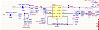
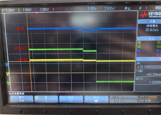
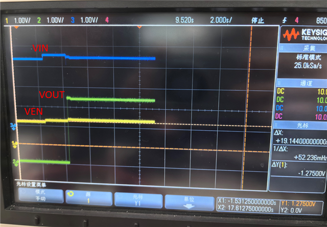
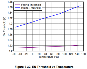
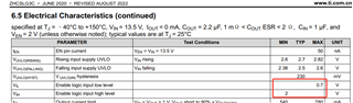
My customer is using TPS7B8650-Q1 and found that the enable logic level is not the same as stated in datasheet. In datasheet VIL=0.7V, VIH=2V, while when testing customer found when input voltage to enable pin > 1.32V, the device will enable and when < 1.22V, it will disable. What is the error for  VIL and VIH value? What are their min and max value respectively?

BR,

Bengi

  • Hi Bengi,

    The right way to interpret VIH and VIL is that this device turns on for EN > 2V and disables for EN < 0.7V. What the customer notices is abnormal. Can you please share their schematic ?

    Regards

    Ishaan

  • Hi Ishann,

    Please see attachment below. When VBB is adjusted to 3V, the measured voltage in FB pin is 1.44V, then customer found that our device is enabled. This is in contract with our datasheet.

    BR,

    Bengi

  • Hi Ishann,

    Today I did test with customer, and find what customer said. Below is the waveform. You can see that when VEN falls below 1.2V, then VOUT turns zero. Note that VIN is above 3V and did not rigger UVLO.

    Below is EN rising waveform. It is the same as I stated in the past. What might be the reason for this?

    BR,

    Bengi

  • Hello Bengi,

    0.7V and 2V are the limits at which we can definitely say the part is OFF or ON. However, the device turns on and off in between these values.

    See the following graph for where you can expect the device to turn on and off. They seem to line up with what the customer is seeing. 

    ~ Aaron