This thread has been locked.

If you have a related question, please click the "Ask a related question" button in the top right corner. The newly created question will be automatically linked to this question.

LM5122EVM-1PH: UVLO Pin Not Turning Off Boost Converter

Part Number: LM5122EVM-1PH
Other Parts Discussed in Thread: LM5122, , LM5121

Tool/software:

Hi Team,

We are currently using the LM5122 Boost Converter in our design, we are using LM5122EVM-1PH Evaluation Kit for development purposes. Our objective is to turn the boost converter on and off using the MCU. To achieve this, we have connected an NMOS transistor to the UVLO pin. This setup allows us to pull the UVLO pin to ground when necessary. Our input voltage is 16.8V, and we have successfully boosted it to 24V. However, we are facing an issue: when we pull the UVLO pin to ground, the converter is not fully turning off. We are still observing the same input voltage at the output, even after grounding the UVLO pin. We verified the voltage at the UVLO pin and confirmed it is at 0V. Shouldn't the converter turn off completely when the UVLO is at 0V?

Could you please assist us in resolving this issue?
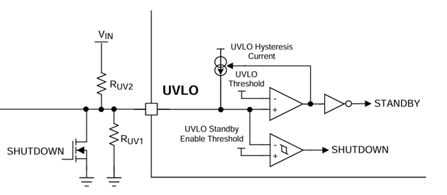


Thanks and Regards
Karthik P R

  • Hi Karthik,

    Thanks for using the e2e forum.

    There is nothing wrong with your approach or the device behavior.
    As you pull UVLO to GND, the device stops switching and enters shutdown mode correctly.

    The problem lies in the topology itself.
    In a boost topology, input and output are permanent connected through the inductor and high side MOSFET. Even if the MOSFET is off, the current can still flow across the internal body diode of the FET. This means even if the controller is inactive, the output voltage will still follow the input voltage.
    If you have 16.8V on the input, I would expect an output voltage level of 16.1V, which is VIN minus the voltage drop of the body diode. 

    If you want an output voltage of 0V when the controller is inactive, you need to disconnect the supply from the power stage.
    For example, LM5121 has such a disconnection circuit already implemented. Here an additional MOSFET disconnects the supply in shutdown mode.

    Please let me know if you have additional questions on either of these devices.

    Best regards,
    Niklas

  • Hi Niklas,

    Thank you for your prompt reply. I just checked the datasheet for LM5121 and noticed it has a dedicated DG pin (Disconnect Switch Control Pin), while LM5122 does not. When I measured the voltage at the high-side MOSFET gate, it was close to my input supply voltage, and the voltage at the low-side MOSFET gate was 0V. Our application requires 24V at 4A, with input options of 16.8V and 24V. Would you recommend using LM5121 for my application?

    Thanks and Regards
    Karthik P R

  • Hi Karthik,

    Thanks for the feedback and confirmation.

    For these specs, LM5121 is a good recommendation.
    We have an EVM board available for this device as well.
    https://www.ti.com/tool/LM5121EVM
    The default settings for Vout are 12V here, but it can be modified to match your specifications.

    Best regards,
    Niklas

  • Hi Niklas,

    Thank you for the recommendation.

    I have reviewed the specifications for the LM5121 board. The evaluation board specifies an input range of 3V to 12V and an output of 12V at 2A. However, my requirements are for an input of 16V to 24V and an output of 24V at 4A. I understand that we can increase the output voltage by adjusting the feedback values, but I would like to know if the other components, such as the switches and inductor, will be able to support my requirements on this evaluation board.

    I also have a question about the LM5122. I'm curious about the Under Voltage Lockout (UVLO) feature in LM5122. If the input voltage falls below the threshold and the output reflects that same voltage, what is the practical application of the UVLO feature in this case? Could you please explain this?

    Thanks and Regards,
    Karthik P R

  • Hi Karthik,

    To check if the components of the LM5121 EVM are sufficient for the new specs, you can always look at the BOM (bill of materials).
    Here you find all component ratings.
    You will see that the FETs are rated for 40V and the output caps for at least 35V.
    This means no components should take damage if you increase Vout to 24V.

    Another large difference is that your application has higher output power (96W instead of 24W).
    This might require a smaller current sense resistor (R2) to avoid triggering overcurrent protection during normal operation.
    For the final design, you might need to consider an inductor with larger saturation current (e.g. 10A saturation current),
    and also keep an eye on the thermal behavior.
    A final step would be adjusting the compensation to match with the new parameters.


    Regarding the UVLO of LM5122:
    While turned on, the device always tries to regulate to the desired output voltage.
    Let's assume we have 48V at Vout and 12V at Vin. Here the operation works fine.
    Now we slowly decrease Vin. If you go down to 6V VIN, you already need twice as much input current to keep Vout stable. Also the bost ratio goes up from 3x to 6x. 
    Now we go even lower to 3V VIN. This would mean four time the input current and a boost ratio of 12x.
    If there is no limiter at the supply and all other protections would be inactive, the board would likely overheat and get damaged, as the device switches with maximum duty cycle to push Vout as high as possible.

    I hope this answers your question why a UVLO protection is useful even for a boost topology controller.

    Best regards,
    Niklas

  • Hi Niklas,

    Thanks for your explanations. I got my answers, so you can close this thread.

    Thanks and Regards
    Karthik P R