This thread has been locked.

If you have a related question, please click the "Ask a related question" button in the top right corner. The newly created question will be automatically linked to this question.

TPS25730EVM: tps25760d

Part Number: TPS25730EVM

Tool/software:

HELLO,

I try to configure the TPS25760D with the EVM module as follow:

- ADC1 SW position to 1 for 5 V minimum input voltage (34..30mV mesured at the center point the resistor divider network)

- ADC2 SW position to 6 for 15 V maximum input voltage (1.894 V measured at the center point of the resistor divider network)

- ADC3 SW position to 1 for 0 Amp minimum sink current (33.98 mV measured at the center point of the resistor divider network)

- ADC4 SW position to 4 for 5 Amps maximum sink current (0.65 V measured at the center point of the resistor network)

- All other switches are on OFF position

-I noticed that all of these value of out of tolerence mentionned into the data sheet for such configuration but 100K resistor from the datasheet has been replaced by 10K in the EVM

-VIN is 12.85 Volts on PINS 23,234,25 on the IC but 0 Volt on its ouput pins 20,21,22!

-LDO 3.3 V and 1.5 V are present on they respective pins

-Sink EN led is bright, all the other led's are off

- A 100 Ohms resitor is connected at J4 for 0.12 Amps sink usually...

-, It looks like the FET switches doesn't want to close inside the chip...

Do I something wrong or missed it ?

Thanks for your help

Kind Regards,

Guy

  • Hi Guy,

    Have you modified the TPS25730EVM in any way?

    By VIN, do you mean VBUS?

    Are any of the ADCIN jumpers missing?

    Can you check to make sure the Fault_in Pin is high?

    - A 100 Ohms resitor is connected at J4 for 0.12 Amps sink usually...

    What does this mean? j4 has many pins.

    Has this EVM worked in the past or was it broken out of the box?

    Thanks and Regards,

    Chris

  • Hi Christopher,

    Thanks for your reply!

    - The TPS25760EVM has not been modified, just try to use it as received out of the box.

    - Vin = Vbus of course!

    - Fault IN pin 18 is high

    - Fault OUT pin 36 is low

    - ADC's switches are configured properly

    - The EVM never worked properly, so I suppose that it is broken from the box.

    What can I do, thanks!

    Kind Regards,

    Guy

  • Hi Guy,

    The EVMs should have been tested before going out, and part of the test involves measuring the PPHV voltage, so I'm somewhat surprised you are seeing this failure.

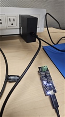
    Could you send pictures of the front and the back of the board when connected to a source?

    I'm assuming you are measuring PPHV at either J1 or the PPHV pins of the male header?


    Can you try the following.

    Configure the EVM with these settings:

    • ADCIN1 : 1000 0000 (switch 1 set)
    • ADCIN2 : 0000 0001 (switch 7 set)
    • ADCIN3: 0100 0000 (switch 2 set)
    • ADCIN4: 0100 0000 (switch 2 set)

    Connect a USB-C PD power supply and see if PPHV shows up.

    If the SINK_EN pin is high, that means the sink path is disabled. It could happen for a variety of reasons.

    For the Type-C power supply you are using, what are the power capabilities? What voltages can it supply.

    Can you test with a different USB-C supply and see if their are any differences? Your phone should be able to offer at least a 5-V source contract for a basic connection.

    Thanks and Regards,

    Chris

  • Hi Chris,

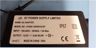
    Please see the pictures attached with power supply and mesurement on My Fluke 45 at the PPHV output => 0VDC with your recommended configuration.

    Pigs.zip

    If the SINK_EN pin is high, that means the sink path is disabled => I agree!

    For the Type-C power supply you are using, what are the power capabilities? => see pictures

    What voltages can it supply. => 12.85 V measured at VBUS

    No change with different PS.

    When I said it doesn't, it doesn't work. I'm sorry.

    I think that I will have to buy an other one from Mouser for 159.06 Euros to test it again before to run our 3000 PCB's production and I'm not totaly happy with that.

    Thanks for your time,

    Kind Regards,

    Guy

  • Hi Guy,

    You might have already tried, but can you remove the load at the screw terminal and try again? 

    ADCIN2 : 0000 0001 (switch 7 set)

    One mistake on my part, can you try with switch 8 set. Setting switch 7 is actually a reserved/unused setting and may cause issues.

    If this doesn't work, you may have to go forward with your last plan. Apologies for the issues here. These are supposed to be tested for basic functionality and come working out of the box.

    Thanks and Regards,

    Chris

  • Hi Chris,

    I did everything you recommended me and finally buy a new EVM directly from TI.

    I carefully configured the module as per chapter 2.7.4 , table 2-10 page 9 of the documentation.

    Applying power source by the USB-C connector, the plug event indicator lights up and 12 Volts DC are applied to the IC input.

    The CAP_Mis indicator doesn't blinks continuously, so it seems to be OK with my PS

    The plug flip LED doesn't lights up when the plug is inserted in one side or in the other

    The output voltage still 0 Volts anyway !

    So I don't know what to do exept to suggest you to try this yourself with an EVM to see if you get the same results like me and get back to me with your results;

    Thank you,

    Kind Regards,

    Guy

  • Hey Guy,

    Even with nothing configured, changed, and no load attached, the EVM failed on arrival?

    I'll also order a fresh EVM so I can test a new one. I have been testing on a separate EVM which should not be modified but I can't replicate your issue.

    If you modify the ADCIN2 pin so the max voltage is 9-V, does the VBUS voltage drop appropriately?

    Is sink_en still lit?

    The EVM should take a couple days to arrive once it gets approved by shipping.

    Thanks,

    Chris

  • Hey Guy,

    I just took another look at the pictures you sent and realized I might know what the issue is.

    Do you have a different USB-C PD power supply you can try? Like a phone charger or a phone?

    I don't think this adapter is USB-C PD compliant, I'm a bit concerned that it only advertises 12V 5-A. Is it an hot plug (12-V when unconnected)?

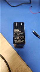
    Typically compliant adapters support at least 5-V. See attached pictures for my setup.

    Could you try with a phone charger or phone?

    Thanks and Regards,

    Chris