This thread has been locked.

If you have a related question, please click the "Ask a related question" button in the top right corner. The newly created question will be automatically linked to this question.

BQ24085: Inquiry regarding charging profile of BQ24085

Part Number: BQ24085

Tool/software:

Hi, TI expert

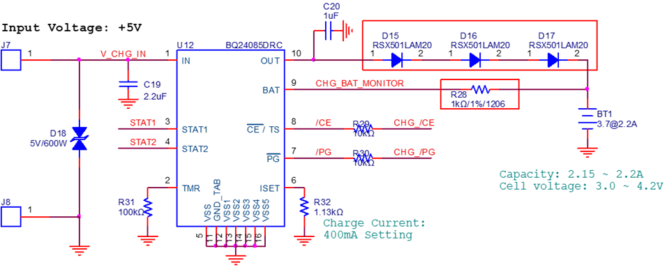
There is an inquiry from a customer about charging profile of BQ24085.

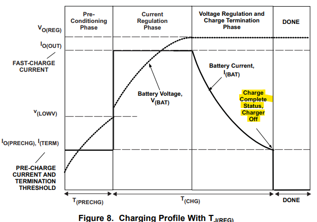
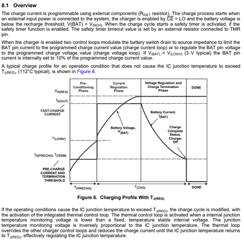
If you look at Figure 8. Charging Profile in BQ24085 datasheet, you can see that Io(OUT) output is supplied and charged to the battery with a steady current until V(BAT) = Vo(REG) is reached, and when V(BAT) = Vo(REG): 4.2V is reached, the current decreases and charging ends.

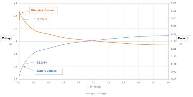
However, during actual measurement, it was confirmed that BQ24085 OUT(10pin) output current decreases when Vbat(9pin) reaches approximately 3.8V.

[Actual measurement graph]

Please check why this part is like that.

If you need any additional information, please let me know.

Thank you.

  • Hello Grady,

    Thanks for reaching out.

    Could you please share the customer's schematic? That will help me look into this further and better understand what might be affecting the charge current behavior.

    Best regards,

    Alec

  • Hi, Alec

    Please refer to the schematic below.

    - BQ24085 Output (10 pin) D15~17 are diodes added to the output pins because they require authentication-related safety elements. (Cannot be excluded)

    [Customer have additional questions.]

    Q1) My initial question (above)

    Q2) In the EV-kit schematic, the resistance connected to the BAT (9pin) is 390Ω, but the actual application was tested with 1kΩ. Is this a problem?

     Is there a recommended applicable resistance range (min ~ max)?

    Q3) I would like to inquire about the minimum input voltage value for charging a lithium battery (MAX 4.2V).

    The battery voltage is charged by controlling the current and voltage through the internal FET of the BQ24085 IC, but efficient charging may not be possible due to the voltage drop of the Power FET, so please check the minimum supply voltage value.

    Please check. Thank you.

  • Hello Grady,

    Thanks for sharing the customer's schematic.

    1. The three diodes between OUT and the battery introduce a significant voltage drop. As a result, the battery never sees the full regulated charge voltage from the charger, which affects how the battery charges. This behavior is expected with those diodes in place.

    2. The BQ24085 datasheet recommends using a 390ohm from BAT to OUT when the output current is under 200mA. The 1k in your customer's design could also be influencing charge behavior, but the main issue is the voltage drop caused by the diodes.

    3. The dropout voltage is 600mV (maximum) for IOUT=750mA and varies with temperature, as shown in Figure 7 in the datasheet.

    I understand the customer may be unable to remove those diodes, but I recommend removing them temporarily to see if the behavior improves. If it does, they may consider alternative solutions to protect their battery.

    Best regards,

    Alec

  • Hi, Alec

    Thank you for response.

    The customer has a further question about answer #3.

    3. The dropout voltage is 600mV (maximum) for IOUT=750mA and varies with temperature, as shown in Figure 7 in the datasheet.

    → The voltage supplied to BQ24085 is dropping due to a fuse, and is being supplied to BQ24085 at approximately 4.7~4.8V.

    If the voltage drops in BQ24085, it is expected that the supply voltage will need to increase by the expected drop voltage. Can you check the drop voltage value when Io = 400mA, 500mA in Figure 7 on the datasheet? (The product's operating temperature is Max 50℃.)

    Please check. Thank you.

  • Hello Grady,

    Dropout voltage is only specified in the datasheet for IOUT=750mA. Figure 7 is intended to show how the dropout voltage varies with temperature. However, dropout voltage decreases with output current, so it's expected to be less than 600mV for IOUT=400mA.

    Best regards,

    Alec

  • Hi, Alec

    Thank you for support.

    This is a further inquiry from the customer.

    Q1) What are the conditions for the Charger to turn off when the battery is fully charged?
    (Customer asking this because I need to set the conditions for the battery to be fully charged.
    Is it overcharged (over 100%) based on the battery's rated charge? Or is it slightly undercharged (under 100%)? Please check.)

    Q2) I want to supply power to the BQ24085 IC using a USB-C connector. I would like to ask whether the default voltage (5V) is output when there is no separate communication after connecting to a voltage-related charging adapter supplied by USB-C type.
    (If I attach a circuit diagram, only the power line is used from the USB-C type connector.)

    Please check. Thank you.

  • Hello Grady,

    1. Charge will terminate when the charge current falls below the termination current threshold (ITERM) or if the charge safety timer expires. The voltage on the ISET pin is compared to V(TERM) to determine when termination should occur. ITERM is set based on RISET, as shown in the table below:


    2. A 5.1k pull-down resistor is required on each CC line for 5V.

    Best regards,

    Alec

  • Hi, Alec

    Thank you for support.

    Referring to the reply, I connected 5.1kΩ pull-down resistors to CC1 and CC2 respectively to ensure that 5V is always supplied for USB-C type charging, as shown in the circuit below. Please check if there are any problems.

    Thank you.

  • Hi Grady,

    Yes, that is correct.

    Let me know if you have any other questions.

    Best regards,

    Alec