This thread has been locked.

If you have a related question, please click the "Ask a related question" button in the top right corner. The newly created question will be automatically linked to this question.

TPS65988: TPS65988DHRSHR charging the DRP from the power only port when both port are connected and related queries

Part Number: TPS65988
Other Parts Discussed in Thread: TPS25751

Tool/software:

Hi,

In our design TPS65988DHRSHR is used for powering up the board, in our design we want to use port 0 as DRP port and port 1 as Power only port.

Queries are following 

1. When we powered the board from power only port (port 1) and the pc is connected to port 0, then the port 1 is trying to charge the port 0 connected pc, how can i avoid this, is there any configuration need to change in the project file.

2.Can we make both the port 1 and port 0 hot swappable means the power should not turned off if any port is removed, now in our case when I remove the DRP port (port 0) even the port 1 power is turned ON the power is going for a second and coming back how to avoid this.

3.After completion of programing of  TPS65988DHRSHR through the GUI  using Aardvark its giving verification failed at the end, but the PD is working fine.

4. Since this part is not recommended for new design suggest a similar part who have similar pin and size which we can implement in our new design so that our layout work can be reduced.

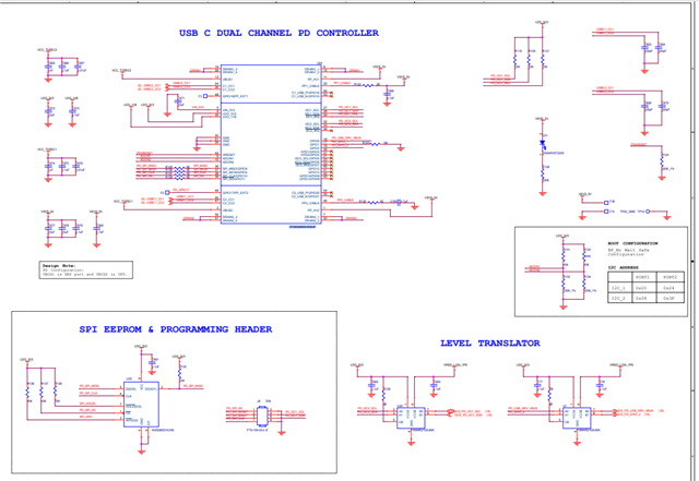
Attaching the schematics and the .pjt file for your reference.

 7534.QCS2290_PD.pjt

  • Hi Anoop,

    use port 0 as DRP port and port 1 as Power only port.

    So Port 0 is Dual role power and Port is Sink only?

    1. When we powered the board from power only port (port 1) and the pc is connected to port 0, then the port 1 is trying to charge the port 0 connected pc, how can i avoid this, is there any configuration need to change in the project file.

    I'm not sure what you mean here. What do you mean by "port 1 is trying to charge the port 0 connected pc"? Where do you want the power to go? Is there any internal power in your design or is all power coming from the type-C port?

    2.Can we make both the port 1 and port 0 hot swappable means the power should not turned off if any port is removed, now in our case when I remove the DRP port (port 0) even the port 1 power is turned ON the power is going for a second and coming back how to avoid this.

    How are each ports PPHV paths connected to system power? When you say power is being lost, is the P1 connection being broken and renegotiated?

    3.After completion of programing of  TPS65988DHRSHR through the GUI  using Aardvark its giving verification failed at the end, but the PD is working fine.

    Do you have a TIVA on your board? The Aardvark can be used to directly program the SPI flash. The GUI does not support flashing the SPI flash directly, and typically does it through a tiva uc found on the EVMs, which is not expected to be replicated on customer systems. TotalPhase has a software called Flash Center that allows you to directly program the EEPROM.

    If you are seeing the correct behavior on the board when you program it, you may be fine, but a verification error could be a concern.

    4. Since this part is not recommended for new design suggest a similar part who have similar pin and size which we can implement in our new design so that our layout work can be reduced.

    Unfortunately there is no direct replacement for this part at this time (pin compatible or not). If already designed in, the TPS65988DH can be used. We will continue to support ongoing projects with this IC. If you only need power and USB3 data, the TPS25751 is the only alternative at the moment.

    Thanks and Regards,

    Chris

  • Hi Christopher Lim,

    Thanks for the reply

    So Port 0 is Dual role power and Port is Sink only?

    Yes Port 0 is DRP and Port 1 is Sink only port.

    I'm not sure what you mean here. What do you mean by "port 1 is trying to charge the port 0 connected pc"? Where do you want the power to go? Is there any internal power in your design or is all power coming from the type-C port?

    Let me clarify the entire system, To the system the power is delivered only through these 2 type C ports, the configuration is in such a way that if any of the power is present in the type C port(DRP or Power only) the system will boot. So issue what we are facing now is when we try to power up the board with both the power only port (port 1) which is connected to type c power adapter and the DRP port (port 0) which is connected to a PC, the system boots but at the same time, the PC is indicating that it is charging which means from the  type c power connected to the port 1 is trying to charge the PC connected to the DRP port 0. I want the power to go to the system. All the power are coming from the type C port there is no internal power in the design.

    How are each ports PPHV paths connected to system power? When you say power is being lost, is the P1 connection being broken and renegotiated?

    Both the PPHV are shorted and this is the input power to the system. The power is being lost means, the PPHV is also connected to LED, for a second it is turning of which means the power is lost which is causing our system to turn off.

    Do you have a TIVA on your board? The Aardvark can be used to directly program the SPI flash.

    No we are not using TIVA in our board, we are using the Aardvark directly to program the SPI flash. 

    Unfortunately there is no direct replacement for this part at this time (pin compatible or not). If already designed in, the TPS65988DH can be used. We will continue to support ongoing projects with this IC. If you only need power and USB3 data, the TPS25751 is the only alternative at the moment

    Ok, Thanks for the suggestion.

    Thanks and Regards 

    Anoop V R 

  • Hi Anoop

    Yes Port 0 is DRP and Port 1 is Sink only port.

    Do you want Port 0 to be Power sink only, but Dual Role Data? We could change the configuration so that it only ever enters as a sink but can process data role swaps.

    If port 1 advertises as a source, it needs to be able to source power. You could consider having it only advertise a very small amount of power, but it would break the PD spec to have it advertise as a source and not be able to source the power advertised.

    Do you have any I2C hosts in the system that can control the PD controller, or is the image only loaded over EEPROM?

    Thanks and Regards,

    Chris

  • Do you have any I2C hosts in the system that can control the PD controller, or is the image only loaded over EEPROM?

    I want port 0 to be DRP which can source the power when I connect a device and sink when I connect a host PC or Type C power adapter. And the port1 to be sink only where Ill be connecting a power adapter.

    If port 1 advertises as a source, it needs to be able to source power. You could consider having it only advertise a very small amount of power, but it would break the PD spec to have it advertise as a source and not be able to source the power advertised.

    Yes this has been taken care, I have configured the max current 500ma.

    Do you have any I2C hosts in the system that can control the PD controller, or is the image only loaded over EEPROM?

    Yes we have our processor connected to PD I2C

  • Hi Anoop,

    Just to better organize, there seems to be two issues:

    (1) Preventing P0 from sourcing when P1 is sinking

    (2) Hot swappable ports when both ports sink


    (1)

    Due to your system architecture, I don't think it is possible to prevent this with the PD controller alone. The issue is that 1: the PPHV1 and PPHV2 pins are connected, and 2: you want P0 to be DRP.

    As mentioned before, if you negotiate a source contract on P0, you must provide the power. 

    There are a couple options you may consider for this issue.

    a. Ensure that the source attached to the P1 port can supply enough power for both the system and the P0 sourcing port

    b. Disable sourcing on the P0 port when you do not want it to take any power. This could either be done through the initial configuration or by using an MCU to write to the P0 PD controller to disable sourcing during specific events.

    Thanks and Regards,

    Chris