This thread has been locked.

If you have a related question, please click the "Ask a related question" button in the top right corner. The newly created question will be automatically linked to this question.

TPS25751: TPS2575D1 || Only Configure for Down stream charging || Host mode

Part Number: TPS25751

Tool/software:

Hi,

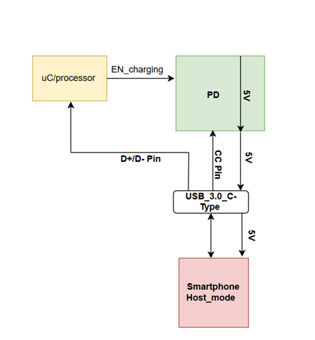
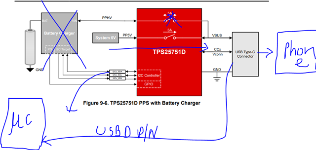
As per our design requirement in Shown in block diagram, We have Charge(5V, 1-3A) the Smart Phone when it is Host mode. we don't  require upstream charging. Can we disable the charging as per user/processor  through I2C Interface?

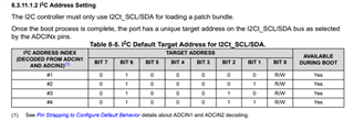
If we can configure Please the configuration setup?

  • and also please confrim, we have required 8 PD ic for 8 smart phone, is that PD have different I2C adress or  all has same address?/

  • Hi Rahul,

    If I understand correctly, you never want the type-C port to do upstream charging? By this, do you mean that the port should never be power role sink?

    If you are fine with the port being sink only, you can customize the configuration in the GUI to prevent the power sink role.

    You can select a source only config and set the data roles to allow swap to UFP.

    PD have different I2C adress or  all has same address?/

    See section 8.3.11.1.2 in the datasheet. There are only 4 unique addresses.

    Thanks and Regards,

    Chris

  • Hi Chris ,

    1. As per below block digram, we required only downstream/source  charging to Smart phone which is control by Controller/user through I2C used in PD.

    2. Regarding I2c address:- Is that required pin ADCIN1 and ADCIN2  need to do high or low configuration in hardware side for 4 unique address combination??

    3. As per our Design, we have to used total 8 PD with Same I2C bus to configured this PD? do we required any I2C multiplex (2:1) ?

  • Hi Rahul,

    1. That makes sense. Yes, the TPS25751 can be configured to be source only from the APP Config GUI.

    There is one challenge from the HW perspective regarding the "dead battery" capability of the device.

    By default the TPS25751 exposes "dead battery" RD resistors on it's CC lines. If the TPS25751 does not have power, it will expose these RD resistors. This allows the part to boot up as a sink and draw power from the Type-C Connector if a USB-C PD source is attached during this time. Unfortunately, the only way to completely disable this would be to add a protection device that isolates the CC lines and that can remove and "dead battery" rd resistors. The TPD4S311A is an example.

    It may not interfere with your behavior, but is something to keep in mind.

    2. Regarding I2c address:- Is that required pin ADCIN1 and ADCIN2  need to do high or low configuration in hardware side for 4 unique address combination??

    Yes, configuration of the ADCINx pins is required. There are 8 voltage levels, and it is recommended to bias the pins using a resistive divider pulled up to the LDO3V3 pin.

    3. As per our Design, we have to used total 8 PD with Same I2C bus to configured this PD? do we required any I2C multiplex (2:1) ?

    If you want to be able to communicate with each of them individually over I2C, there are only 4 unique addresses, so yes, you may need to find a way to multiplex devices with the same address.

    Thanks and Regards,

    Chris