This thread has been locked.

If you have a related question, please click the "Ask a related question" button in the top right corner. The newly created question will be automatically linked to this question.

TPS23881: PSE Controller for four 4-pair RJ45 ports

Part Number: TPS23881

Tool/software:

Hi Team,

We are using the TPS23881 PSE controller and successfully achieving 90W through a single port. We are now planning to achieve the same power output across 8 ports. Is it possible to scale up the existing code to support all 8 ports?

Looking forward to your response.

  • Hi Iaya,

    Thanks for reaching out. We will take a look on your question and get back to you in 3-7 business days. Thanks for your patience.

    Best regards,

    Diang

  • Hi Iaya,

    Thanks for your patience. 

    1 x TPS23881 has 8 channels, and for 90W Type-4 Class-8, the 802.3BT standard needs a 4-paris port which needs 2 channels for TPS23881. In your case if you want to output 8 x 90W ports, you will need 2 x TPS23881 chips. 

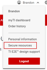
     The code SRAM code can be requested by clicking "request now" in https://www.ti.com/product/TPS23881 And they will be available in your "Secure resources" after approval. 

    If you want to run non-host autonomous mode, which does not need a MCU controller to load SRAM and PSE can output 90W when powered on, you can use TPS23881B which is pin-pin to TPS23881 and configure its AUTO pin. 

    Best regards,

    Diang

  • Hi Diang,

    Thank you for your time and support. We will review this and follow up with you if further discussion is needed.

  • Hi Diang,

    Thank you for your response.

    Currently, we are using two PSE controllers to achieve a 90W output across 8 ports, with each PSE controller managing 4 ports. The I2C addresses assigned to the PSE controllers are as follows:

    • First PSE Controller: Addresses 20 (Initialization) and 21 (Monitoring)
    • Second PSE Controller: Addresses 22 (Initialization) and 23 (Monitoring)

    We have modified the code so that addresses 20 and 22 are used for initialization, while 21 and 23 are designated for monitoring purposes.

    Could you please review this approach and share your insights on whether this setup is optimal for our scenario?

    Looking forward to your feedback.

  • Hi Jaya,

    Can you clarify by using addresses 20 and 22 for initialization and 21 and 23 for monitoring? What is meant by monitoring?

    TPS23881 can be configured in Config A (8-bit mode) or Config B (16-bit mode) which is configurable using the GENERAL MASK register (17h). The difference between 8-bit and 16-bit mode are as follows:

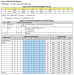
    • Configuration A (8-bit) mode gives 8-bit access, therefore the 8 channels are treated in quads as 2 independent consecutive I2C addresses in order to sevice all ports. Channels 1-4 will be the EVEN I2C address based on the A4-A1 pin programming and Channels 5-8 will be the ODD I2C address. This is determined by the A0 pin status, for example in 8-bit mode Channels 1-4 are addressed with 0x20 and Channels 5-8 are addressed with 0x21.
    • Configuration B (16-bit) mode gives 16-bit access to service all 8 channels with a single address where A0 is always 0. Therefore, you can configure all 8 chanels (4-ports) using 0x20 in this case.

    For your approach, you should not need to use different address for initilization and monitoring, these should be done using the same address, just changing what you are reading/writing from. For instance, you would utilize the RO register to access information for "monitoring" and use the R/W access register (generally speaking) for "initialization."

    Regards,

    Brandon

  • Hi Brandon,

    In our case, we are following 8-bit mode since we will have separate lower and higher addresses. We refer to the I2C addresses as 0x20 and 0x21 for the first PSE controller and 0x22 and 0x23 for the second PSE controller. These addresses are determined by the A0 pin status.

    Our approach in the code is to configure both PSE controllers, each with 8 ports, to deliver 90W per port. By "monitoring," we mean retrieving key parameters such as: Voltage, Current, Power faults, Classification status.

    Regarding your question about initialization and monitoring using different addresses, we do not need separate addresses for these operations. The same I2C address should be used, with different register access methods:

    • Initialization: Uses R/W registers to configure the PSE controller.
    • Monitoring: Uses RO (Read-Only) registers to fetch real-time status and fault conditions.

      Looking forward for your valuable reply.
  • Hi Jaya,

    Just to confirm, the addresses in this scenario will be determined by the A1 pin. When this pin is ground along with Pins A2,A3, and A4 the result I2C addresses will be 0x20/0x21. When the A1 pin is floating (internally pulled to Vdd) or pulled high and A2,A3, and A4 grounded you will result with address 0x22/0x23. The SLA0 bit is the signifier for the quad you are referring to in 8-bit mode.

    In terms of initialization and monitoring, yes you are correct and this will work no issues. Should be no issues with your plan just wanted to confirm the above, thanks!

    Regards,

    Brandon

  • Hi Brandon,

    Thank you for your explanation. We will review this internally and get back to you.

  • Hi Jaya,

    I will close this thread for now, please feel free to open another thread if you have additional questions.

    Regards,

    Brandon

  • Hi Brandon,

    We referred to this link www.ti.com/.../SLVC771 for the 4-port PSE controller.

    Could you confirm if this code is suitable for our implementation, and can we use it as a reference to support a 4-port configuration?

  • Hi Jaya,

    Yes, that code is suitable for basic implementations, I would also recommend updating the code to the latest SRAM version release. SRAM code can be requested via the TPS23881 product page here:

    Once approved, you will navigate to "Secure Resources" under your profile name at the top.

    Once you have the latest SRAM downloaded, you can port this into the reference code.

    Regards,

    Brandon