Tool/software:
Hello, I am Sunny.
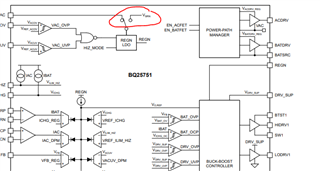
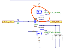
I have a question about BATFET control.
The pin BATDRV drives the BATFET gate with 10V relative to BATSRC to turn on BATFET. But in the system, the battery is used as the system power only when the system power is off. In this condition, BQ25751 will not have power as its power is from system power. Then, the pin BATDRV will not output and the BATFET cannot be driven, right? If so, could you help give me some suggestion to realize this function?
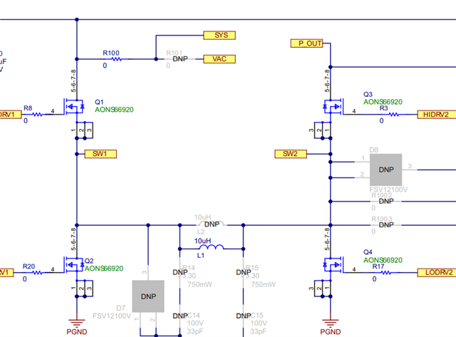
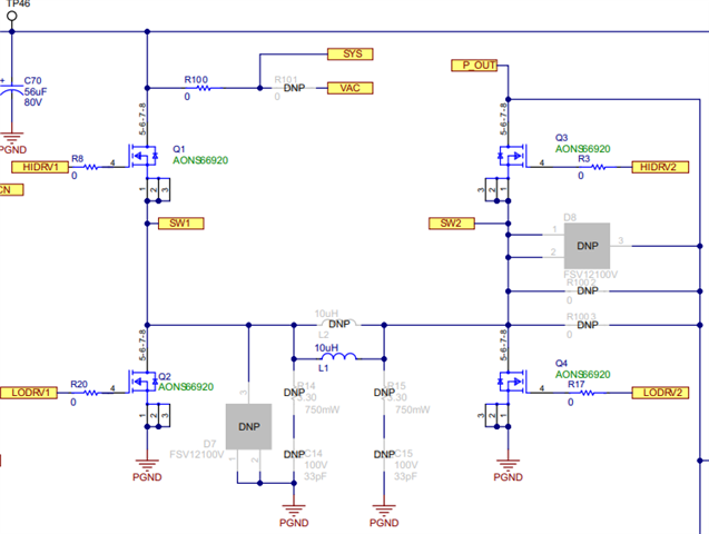
For buck-boost charging, if I only want to use its buck charging mode, how can I design this part? Can I not load Q3 and Q4 and load the R1003? Or any other advice?
Hope I can receive your reply soon.
Thanks a lot.