Tool/software:
Hi,
I have two questions:
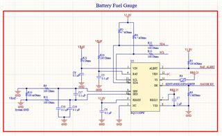
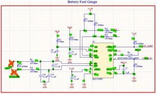
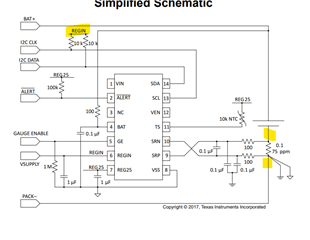
- Can you provide a design review of the schematic shown below? VBAT: 3.6V, Processor voltage: 1.8V
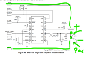
- Can you provide a bit more details on how the sense resistor ties into ground? My understanding is the negative terminal of the battery is only connected to one side of the sense resistor. The system ground is connected to the other side of the sense resistor. Please confirm this is the correct understanding. If you have examples that help illustrate the best way to tie this to the board would be helpful.