Tool/software:
Hi,
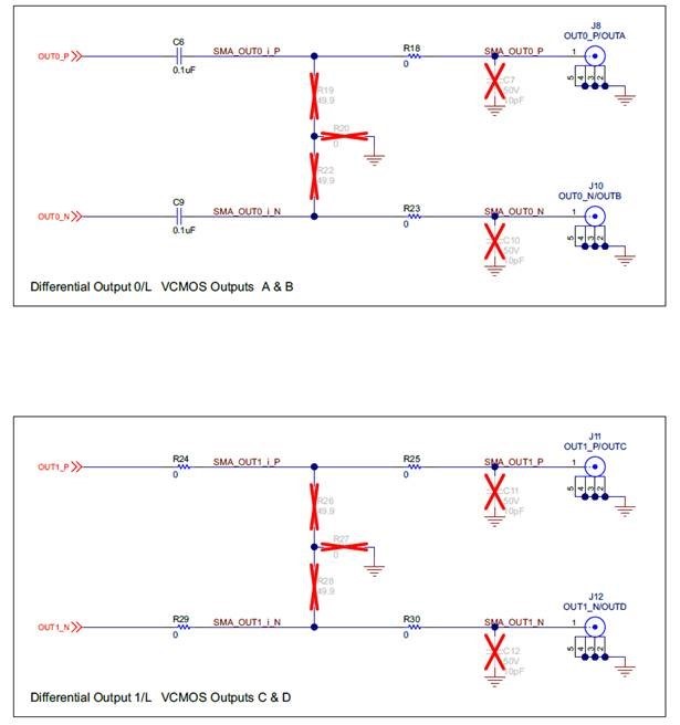
We found EVM schematic P32 why is the component configuration different for Output Channel 0 and 1?
For OUT0 P/N, resistors (R) and capacitors (C) are used, while for OUT1 P/N, only resistors (R) are used.
What is the purpose of this difference? And what is the purpose for reserve this RC? Thanks!