


Other Parts Discussed in Thread: BQ25798, ,
Tool/software:
Hi,
It is the first time I have used TPS25751+BQ25798.
I want to know correct test procedure.
If there is wrong, please let me know.
1. Flashing Configuration onto TPS25751EVM, refer to figure1
1.1. Connect J4 Type-C connector with a cable to computer.
1.2. Connect J2 Type-C connector to supply VSYS (15-20V), in order to get PP5V & P3V3.
1.3. Open the Application Customization Tool and setting configurations, then export xxxx.bin.

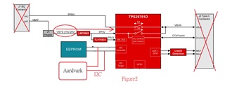
2. My own TPS25751+BQ25798 PCB board., refer to figure2
2.1. Add DC source to supply VSYS (15V-20V). In order to get PP5V & P3V3.
2.2. Write to EEPROM (xxxx.bin) by Aardvark I2C/SPI Host Adapter.
2.3. Remove Aardvark & DC source.
2.4. After writing the EEPROM, connect J3 Type-C connector to start the board.
thank you.
Mulin
