This thread has been locked.

If you have a related question, please click the "Ask a related question" button in the top right corner. The newly created question will be automatically linked to this question.

UCC28056: Random OCP Triggering & Secondary Fuse Blowing During 3kV Surge

Part Number: UCC28056

Hello TI Team,

We are using the UCC28056CDBVR in our design and experiencing an issue where overcurrent protection (OCP) randomly activates during 3kV surge testing.

The problem is that OCP subsequently triggers OVP2, which activates a safety mechanism that blows the secondary fuse whenever the load gets disconnected.

Due to this, the fuse is blowing during surge hits.

Design Details:

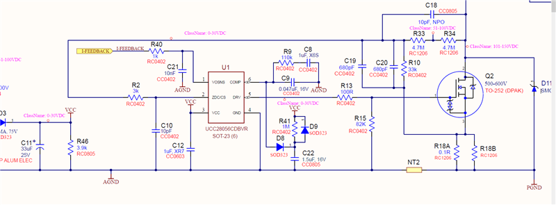
  • CS Resistor (Rcs): 0.1Ω
  • RC Filter on CS Pin: 3kΩ + 10pF
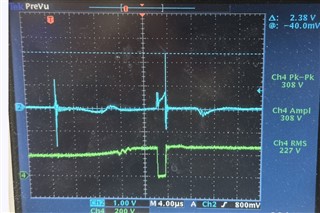
  • Issue Observed: High-frequency noise on the CS pin (oscilloscope image attached).

Scope Setup:

  • Blue waveform: Voltage across Rcs

Key Observations:

  • The CS pin exhibits high-frequency spikes 
  • Despite the internal 150ns leading-edge blanking (LEB), these spikes seem to cause false OCP triggering.
  • OVP2 activation leads to load disconnection, resulting in fuse failure.
  • Increasing Rcs is not an option as it impacts other tuned performance paramters.
  • Soft start adjustments are constrained by the  startup time requirement.

Questions:

  1. How can we prevent random OCP2 activation during surge transients?
  2. Is there a way to disable or modify OVP2 behavior to avoid fuse blowing?

Attachments: Oscilloscope capture of CS voltage spikes.

Thanks in advance!

  • Hello Reddy, 

    I can agree that 3kV surge testing may instigate an OCP response by the UCC28056C if the conditions to trigger OCP1 or OCP2 are met during the surge. 
    I disagree that the OCP is random.  Clearly each OCP response can be correlated to a surge pulse. 

    There is no link between either OCP response and an OVP2 response within the IC.  They are independent faults and if an OVP2 response happens, it would also be correlated to having the appropriate OVP2 conditions met during the 3kV surge, regardless of what happens at the CS input.  

    Finally, there is no particular output signal that indicates an OVP2 condition, so I don't see how anything the UCC28056C does can directly trigger a circuit that disconnects the load or blows the fuse.  Except for one thing: If the PFC switching is shutdown for 1 second due a "long-fault" (OCP2 or OVP2) and your circuit detects that the output voltage has fallen below some threshold and then disconnects the load and blows the fuse.   
    One other possibility is that it the surge may be directly perturbing your circuit and triggering the load disconnect. 

    Line surges introduce high dv/dt and high peak currents that course through the PFC circuit and can couple noise to control signals.  
    Ideally, the current paths and dv/dt coupling are controlled and kept away from sensitive signals. 
    If some noise does get through, it must be filtered or clamped.  

    LEB is active only during the immediate interval at the start of the MOSFET on-time.  It does not blank the CS input at any other time. 
    OCP is detected at the ZCD/CS input during the MOSFET on-time; OVP2 is detected at the same pin during the MOSFET off-time within timing constraints discussed in Section 8.3.5.3 of the datasheet.  In each fault case, the fault must recur in three consecutive switching cycles, therefore filtering is not an option. 

    Clamping the signals to keep the peaks below each OCP2 and OVP2 threshold could work except that it will also prevent detection of legitimate OCP2 and OVP2 conditions.
    This would not be an easy decision to make. 

    I recommend to examine your pcb layout and rearrange the tracks to guide surge currents and voltages along paths that will not couple to or interfere with control signals. 

    Regards,
    Ulrich

  • Thank you for your response. The load is being disabled due to the 1-second shutdown triggered by OVP/OCP conditions, primarily during 3kV 90-degree+ surge hits. We have added the SMCJ200A TVS diode across GND & DRAIN, chosen due to its clamping voltage being suitable for our max working voltage of 135VAC, which has helped reduce the frequency of shutdowns, but it hasn't completely solved the issue.

    We cannot modify the fuse blow mechanism as it is part of the intended design specifications. However, do you have any recommendations on how to eliminate the 1-second turn-off behavior during these surge events? Any suggestions on additional clamping or filtering techniques would be greatly appreciated. We will also review the PCB layout as you suggested.

    Looking forward to your thoughts.

  • Hello Reddy, 

    Thank you for the additional information about your application, and for confirming that the controller preforms a 1-second shutdown.
    That narrows the problem to OCP2 and/or OVP2.

    Since a 200V TVS seems to reduce the occurrences, it suggests that OVP2 is the likely cause of shutdowns, but it is not definitive. 

    It is also useful to know that your PFC is < 200V output. 
    I suspect that your Kzc ratio is around 200 rather than the usual 401. (See paragraph just  above Equation (57) in the datasheet.)
    Can you please verify that?  If it is ~200, then the OVP2 threshold is effectively lower at 1.125V x 200 = 225V, for example. 
    (The actual OVP2 voltage depends on your actual Kzc factor.)

    To prevent OVP2, you must prevent the ZCD/CS voltage from exceeding 1.125V during the MOSFET Off-time.  
    Your 200V TVS appears to be partially effective at doing this, so the peak signal appears to be marginally close to 1.125V.
    I suggest to keep the 200V TVS in place, but add an additional clamp part-way down the ZCD resistor divider in order to prevent Vzcd from getting higher than 1.10V.   That clamp voltage can be any convenient value (such as 5V or 12V, for examples) provided that the clamp does not steal any significant current from the ZCD divider string. 
    This requires you to spilt the lowest Rzc1 resistor into two values where a zener diode (such as 12V, for example) is inserted to prevent the ZCD/CS pin voltage from rising higher than 1.10V.  The zener diode must draw <1uA from the divider string.  
    If a zener cannot be found that holds a tight voltage at <1uA, then the zener cannot have direct connection to the divider.  Instead, It must have a separate resistor to Vout to provide bias current for the zener voltage and use a 1N4148-type diode to connect the ZCD divider to the zener clamp.   

    I think you will also have to split the capacitor divider on ZCD/CS as well, so that the capacitor divider voltage can also be clamped by the zener. 
    You don't want the capacitor network to couple the surge voltage around the zener clamp. 
    Follow the same design principle as discussed in the datasheet around Equations (55) and (56). 

    All of the above assumes that the problem involves OVP2.  
    If the problem is actually from OCP2, then the solution may be more complicated, because the OCP2 threshold is much lower (as low as 670mV at the CS pin).  In this case you would need to clamp ZCD/CS voltage to < 0.67V but not lower than 0.55V and only during the MOSFET on-time. 

    A clamp voltage of 0.60V +/-5% (not 10%) under all conditions would be a good target to achieve, but it can only be activated when DRV voltage is high (MOSFET is on).  I don't know how to actually implement this, but that is my suggested target to solve OCP2.   
    Let's hope the problem is due to OVP2. 

    Remember that clamping either of these signals removes the 2-level protection function from your system. 
    That must be acceptable, or their functions recreated (without surge susceptibility) externally.

    Regards,
    Ulrich

  • Hi Ulrich,

    Thank you for the detailed explanation and recommendations. Your insights on OVP2 and OCP2 behavior make a lot of sense. I will try your approach and see how it impacts the issue.

    I have attached the schematic for your reference. Please let me know if you have any further suggestions.

    The PFC Voltage is less than 200V and Kcz ratio is 285.

    Appreciate your time and support.