This thread has been locked.

If you have a related question, please click the "Ask a related question" button in the top right corner. The newly created question will be automatically linked to this question.

LP5012: No LED output, but i2c working

Part Number: LP5012
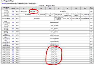
Other Parts Discussed in Thread: LP5812

Tool/software:

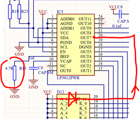
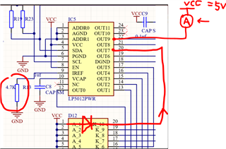
I have a LP5012 on my board and can write and readback registers via i2c, but no matter what I set I don't seem to be able to get any output. My understanding is that from a default state (and I have tried setting the  reset to defaults register) the only requirements to get a light would be to enable bit6 of register 0 and pull the EN pin high. my EN pin is tied to VCC (5V). When I write and readback register 0 it changes from an initial 0x00 to 0x40 (seems correct)

I have tried setting all the brightness to 0x80 to try and get some output, I tried changing all the setting in register 1 and 2 but never get any output.

R-iref is 4.7K ohms, but I tried bypassing it to use the internal current limit

measuring the voltage on the output pin I get with on an oscilloscope with an LED to VCC shows 3.5V but no waveform and the LED does not light (looks like about the voltage drop of the LED I guess)

my i2c pullups are 4.7K, but i2c is working anyway so that seems irrelevant

I tried replacing the IC, but no change

I have tested my LEDs themselves 

  • Hi Matthew,

    After powering up the device, only need to write 2 registers that should turn on the LED.

    1. enable chip, write 0x40 to register 0x00;
    2. set OUTx pwm value, write the non-zero value to the OUTx_COLOR registers (from 0x0B to 0x16)

    Then the outx should turn on.

    Best regards,

    Felix

  • that's about what I thought, although as it says "00h = The colour mixing percentage is 100%" I thought 0x00 was fully on, regardless, at 0 and 0xff there is no output, none of the LEDs light and an ammeter put between VCC and the output pin shows 0mA

  • Hi Matthew,

    I suppose you have connected the 4.7k resistor to the IREF, correct?

    Besides that, have you tried to read back the write value to the OUTx_COLOR register?

    Best regards,

    Felix

  • yes. I just checked the resistor does measure as 4.7K and on the IC side its 0V when Chip_EN is off, 0.7v when its on. the diode you have drawn is where my LEDs are, I had intended to use a bar graph but don't have the part yet so I just have a bunch of regular LEDs installed.

  • Hi Matthew,

    Have you checked the OUTx_COLOR register value after write? 

    When the chip_en = 1, the OUTx_Color = non-zero value and all remaining registers value are left as default (LEDx_Brightness should also be non-zero value), there should be output current.

    Best regards,

    Felix


  • I have been writing registers with my logic analyzer, and I have verified that what I write gets read back, if I change what I write I read back the changes and if I reset the board the registers all read as defaults. if I write one register at a time I still get the same results and I switched to this method after I were doing the same on an AVR but having to reprogram it every time.

    to try to make sure I weren't missing a problem with my board I put my multimeter on mA between vcc (5V) and a few of the output pins directly on the IC, always read zero. most have LEDs connected but one is open circuit (I cut the LED off so I had a convenient place to measure current)

    I double checked that my 5V is in fact 5v (4.989V)

  • Hi Matthew,

    The command write should be no problem.

    From my understanding the current meter is placed between output of LP5012 and the VCC, correct?

    And you have measured the 0.7V on the IREF pin of LP5812, correct? Could you also help to measure the voltage on the VCAP pin?

    Besides that have you checked whether the OUTPUT of LP5012 is connected well to the routing on the baord?

    Best regards,

    Felix

  • yes the meter is as you have shown, I tried both a convenient spot on the board but also a probe direct on the pin of the LP5012, in case it was a solder issue. 
    Vcap measures about 1.8V

  • Hi Matthew,

    Yes, I also think it may be a hardware issue. Could you share an image of the real board connection?

    Best regards,

    Felix

  • OK, got it, sort of anyway. when I were preparing the photos for this I did more damage and decided it was time I redid the board, I now have a board with lights I can turn on an off, I'm not done yet, but I'm done with this issue. I still have know idea what was wrong, maybe a short under the IC but it seems odd that even after replacing the IC I had the exact same problem, still, works on my new one. these aren't particularly sensitive to heat are they? any IC will die if you get it how enough but that's generally pretty hard, I did try to reduce the heat this time, but I don't think I really did much different to the first 2 times.