


Other Parts Discussed in Thread: TPS61070, , TLV61070A
Tool/software:
Hi there,
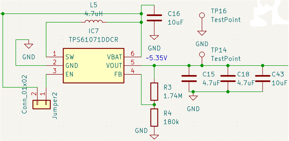
I am using TPS61071DDCR to generate a 5.35V from an input of 3.3V to 4.2V. The schematics is as follows. In the first test, I used R3=1.74Mohm and R4=180kohm. When there is no load (nothing is connected to the output pin except the oscilloscope), the output is normal. When I loaded the output with a 24ohm resistor, the output voltage dropped a lot. So I checked the reference design of TPS61070 (TPS61070EVM-062 User's Guide), and revise R4 to 100kohm and R3 to 1Mohm, and got the same results. But when I first power on the chip without loading, and then connect the 24ohm load, the chip works normally.
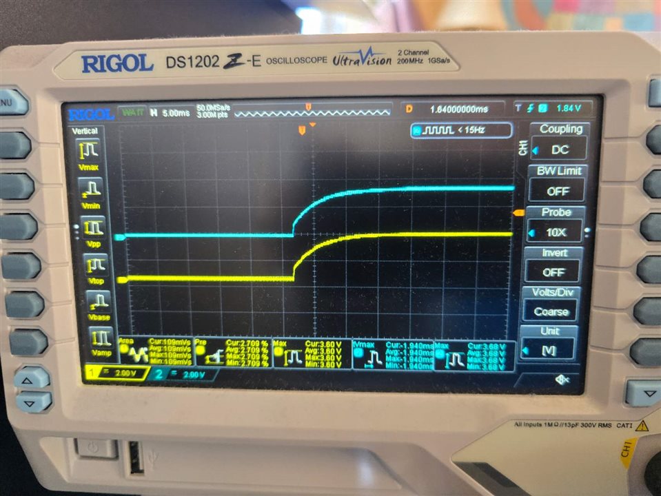
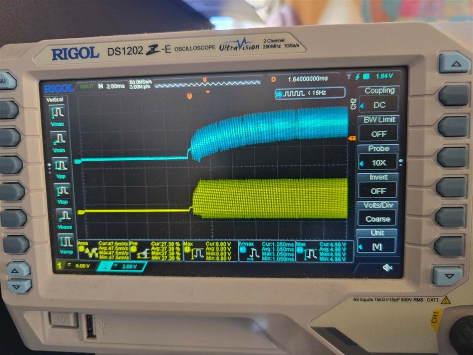
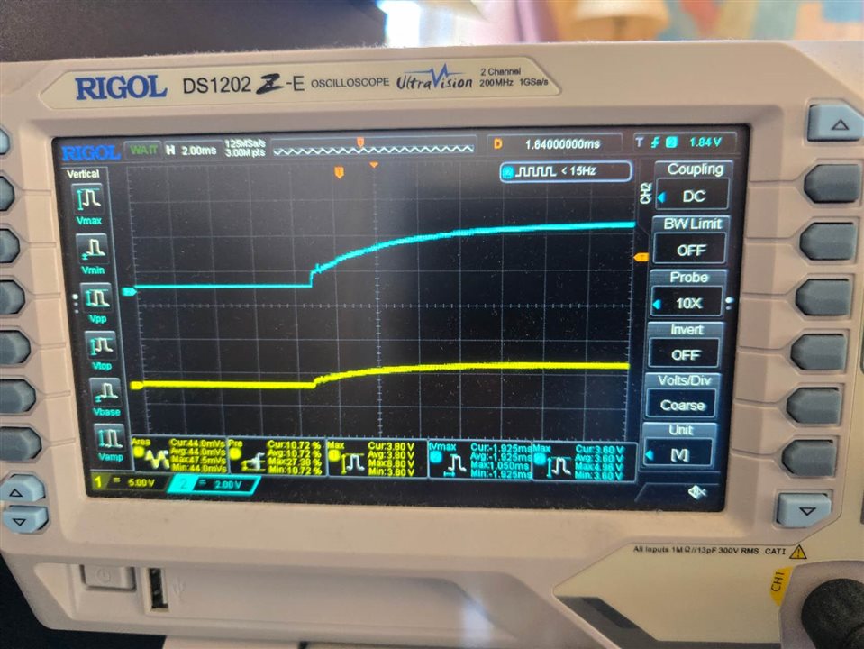
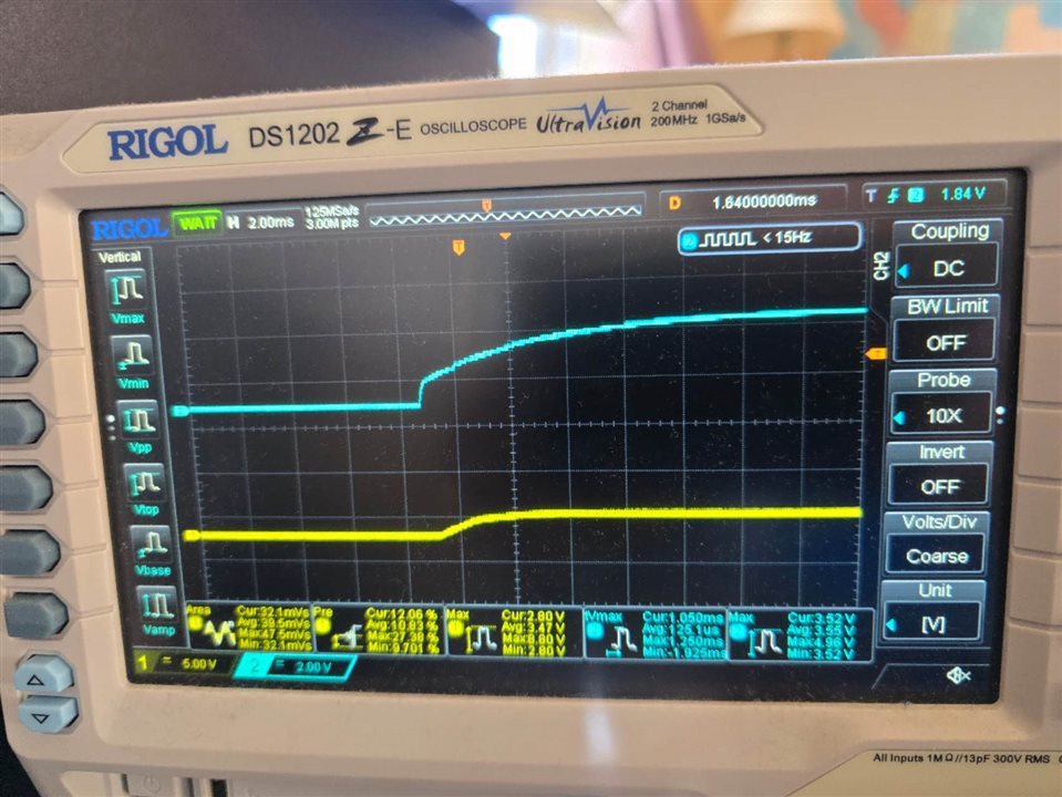
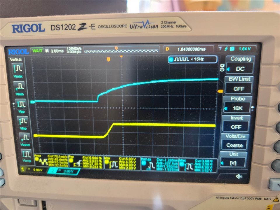
I captured some waveforms, my oscilloscope has only two channels, I used input as the trigger channel (channel 2, the blue 1), and channel 1 for other signals.
Figure 1 channel 1 is for SW with 24 ohm load;
Figure 2 channel 1 is for SW without load;
Figure 3 channel 1 is for EN without load;
Figure 4 channel 1 is for EN with 24 ohm load;
Figure 5 channel 1 is for output with 24 ohm load.
Would you please help me out?
Thanks a lot,
Zhonghai
(1)
(2)
(3)
(4)
(5)

