This thread has been locked.

If you have a related question, please click the "Ask a related question" button in the top right corner. The newly created question will be automatically linked to this question.

UCC25660: ISNS has an indefinite value when turned on

Part Number: UCC25660
Other Parts Discussed in Thread: UCC25600,

Tool/software:

Hi all,

My customer has a question.

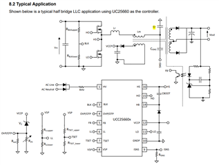
When turn-on, ISNS pin's current exceeds the absolutely value and the device stops by OCP.

Is the value wrong? If there is any way to suppress the fluctuation, please let me know.

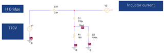
[Each value]  (refers to the circuit diagram below)

Vin=770V, Vout=14.4V/600W

Lr=85uH

Lm=510uH

C=0.03uF

CISNS=110pF

RISNS=180Ω

Best Regards,

Ryusuke

  • Hi Ryusuke,

    Could you share the schematic and design calculator and the waveform?

    Regards

    Manikanta P

  • Hi Manikanta,

    Thank you for your reply. I send the schematics and waveform.

    My customer tested Cisns and Risns with various constants, but the results were the same.

    They tested 10 patterns between 25 pF and 470 pF for Cisns, and adjusted Risns for Cisns.

    This indefinite value comes out according to the variation of transformer voltage (dv/dt).

    Is it difficult to specify for applications with high voltage input (770V)?

    I would appreciate any advice.

    Best Regards,

    Ryusuke

    shematics and waveform.pdf

  • Hi Fukunaga,

    The HS pin of the IC needs to be connected to switch node voltage for the adaptive dead time to work. Also. the controller can handle up to 600V Input voltage.

    Use UCC25600 for this application which doesn't have any adaptive dead time.

    Regards

    Manikanta P

  • Hi Manikanta,

    I update the shematics and waveform.

    shematics and waveworm_2.pdf

    My customer uses the HV terminal connected to the GND with reference to the thread below.

    (+) UCC25660:Comparison document between UCC25640 and UCC25660 and HV PIN design of UCC256603 - Power management forum - Power management - TI E2E support forums

    Also, the gate driver is driven through the pulse transformer. They use a full-bridge circuit. and they can switch the FET without any problems.

    However, because of layout problem, they cannot connect the HS pin to the switch node.

    1) Is it correct to understand as follows?

    That the HS pin is not directly connected to the circuit → Deadtime optimization is not possible → SNS pin is indefinite?

    2) Is it not recommended this usage?

    Since the waveform is indefinite value at the turn-on timing, so I think that the inductor current that changes rapidly during the deadtime is causing high-frequency noise at the ISNS pin.

    3) Is it possible to cancel the high-frequency noise by increasing the capacitance value of the capacitor?

    If so, what are the recommended capacitance values for the 110 pF and 100 pF capacitors in the shematics?

    4) The HV terminal is connected to GND. Can the soft-start function work even if there is no voltage input to the HV terminal?

    Best Regards,

    Ryusuke

  • Hi Ryusuke,

    You cannot connect HS pin to GND for this controller. This would make the dead time maximum. So, circuit won't be operated properly. As I mentioned before, you should not use this controller for this application. You need to use UCC25600. Please setup a webex meeting for further questions.

    Regards

    Manikanta P

  • Hi all,

    I understand that it is not recommended to connect the HS connector to the GND.

    1) What does ‘’ ’You need to use UCC25600‘’ mean? Which model number should I use?

    2) Is it possible to reduce the high-frequency noise by increasing the capacitance value of the capacitor?

    If so, do you have the recommended capacitance values for the 110 pF and 100 pF capacitors in the shematics?

    3) The HV terminal is connected to GND. Is it possible to work soft-start function even if there is no voltage input to the HV terminal?

    Best Regards,

    Ryusuke

  • Hi Ryusuke,

    UCC25600 is a another LLC controller : UCC25600 data sheet, product information and support | TI.com

    2) Is it possible to reduce the high-frequency noise by increasing the capacitance value of the capacitor?

    If so, do you have the recommended capacitance values for the 110 pF and 100 pF capacitors in the shematics?

    100pF is okay at the ISNS pin.

    3) The HV terminal is connected to GND. Is it possible to work soft-start function even if there is no voltage input to the HV terminal?

    By shorting HV pin to GND, there wont be any HV startup function.

    Regards

    Manikanta P

  • Hi Manikanta,

    1) Can't you recommend the circuit I sent?  Can I connect the HS pin to the GND if the Adaptive Dead Time function is not used?

    So the FET can be switched, I think it can be used without the function.

    2)Regarding the cause of the spike that appears in the ISNS, I think it is not because the Adaptive Dead Time does not work.

    The circuit model of the current detection circuit is shown below.

    The integrated value of the current flowing into the 33 nF capacitor is the terminal voltage of the capacitor.

    The differential voltage value of the 33 nF capacitor voltage is obtained at 110 pF and 180 Ω.

    Since the voltage is proportional to the current flowing into the 33 nF capacitor, the current can be measured.

    However, the problem with this circuit is that the other terminal of the capacitor is connected to the H Bridge, and it makes a square wave transition between

    0-770 V. The voltage transition passes through the differential circuit and reaches the ISENS terminal of UCC25660.

    Is this Idea correct?

    Best Regards,

    Ryusuke

  • Hi Ryusuke,

    If you connect the HS pin to gnd, the fets will still switches. However, the dead time would be default dead time which is 1us. Due to this, you would see unstable switching pattern. So, you shouldn't use the IC with HS pin connected to GND.

    Regards

    Manikanta P

  • Hi Manikanta,

    Thank you for your answer.

    Let me confirm one thing.

    What is the '' unstable switching pattern ''? Is it correct to understand that the VGS and VDS waveforms of the FET become unstable?

    ''Even if it is not unstable at first, it will become unstable if they continue to connect the HS pin to GND.''

    Is it correct to understand?

    Best Regards,

    Ryusuke

  • Hi Ryusuke,

    What I mean is, for a given resonant tank for a given input and output voltage, the switching frequency needs to be a certain value. Now, since you connected HS pin to GND, the controller wont be able to achieve the required switching frequency demanded by the feedback. So, you would see unstable switching pattern.

    Regards

    Manikanta P

  • Hi Manikanta,

    Thank you for your response. I appreciate it.

    Best Regards,

    Ryusuke