This thread has been locked.

If you have a related question, please click the "Ask a related question" button in the top right corner. The newly created question will be automatically linked to this question.

BQ25756: I2C communication issues in Boost Mode

Part Number: BQ25756
Other Parts Discussed in Thread: USB2ANY, EV2400

Tool/software:

I am experiencing intermittent I2C communication failures when using the BQ25756 in boost mode. The device is being used in a custom board, controlled by an STM32H7 mcu. The issue does not occur when operating in buck mode, only when charging in boost mode begins.

I2C Failures:

  • Communication randomly fails with arbitrary loss errors and timeouts.
  • The failures appear sporadically—sometimes communication works fine, and then it fails again.
  • In rare cases, the device continues to respond over I2C, but the data read from it is incorrect (e.g., wrong register values, unrealistic measurements).

I've tested different I2C clock speeds and the issue persists at all speeds. I've also checked the fault registers but no relevant faults were reported.

I'm guessing that the problem is related to switching transients that affect the I2C operation. Is there a known issue with I2C stability in boost mode? Are there any recommended design guidelines or mitigations to improve I2C reliability in boost mode? What is the recommended procedure to reset the device in case it "crashes"?


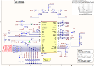
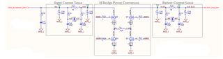
Let me know what other information you'll need to provide support. I've attached a schematic of the BQ25756 connections

  • Hello Federico,

    Thanks for working with this.

    Is there a known issue with I2C stability in boost mode?

    There's not a known issue of I2C stability in boost mode.

    Are there any recommended design guidelines or mitigations to improve I2C reliability in boost mode?

    We don't have any recommendations yet.

    What is the recommended procedure to reset the device in case it "crashes"?

    I've got a few questions to help debug this:

    • What registers are you seeing that are reading wrong?
    • What type of I2C errors are you seeing?
    • If possible, can you send me your layout? You can send me a friend request over the E2E forums and that will allow you to message the layout to me directly if you want.

    Best Regards,
    Ethan Galloway

  • Hello Ethan,

    Thanks for replying.

    I was reading only the following registers: IAC, IBAT, VAC, VBAT, TS, Charger Status 1 and Fault Status; and writing on the register Charger Control to reset the watchdog and enable/disable charging. These are the ones being read/written periodically. I omitted the ones I configure only once during startup. 

    I am trying to get a logic analizer connected to the board to monitor closely what actually happens, but for the moment I can only give you what I see from the software side. When I2C communication starts to fail, I get Arbitration Loss errors and sometimes, timeout error. 

    One of the issues we are encountering is that, sometimes the device interrupts the charging process for a second (more or less) and then restarts it. We can confirm that from external ADC measurements and from what we see in the power supply. The fault registers don't show any faults (are the faults latched in these registers? since we are having I2C communication errors, I am not sure if I can read in time the fault when it happens, so if the register then resets, maybe I am missing the error).

    Some other times the device just "crashes". I2C communication does not show any errors, but the measurements are all wrong. Charger status shows Trickle charge phase, current measurements are fixed around 0.07 Ampere and voltage measurements are also fixed to some value. But, comparing them with the external ADC measurements and power supply, they are all wrong. In some cases, the Fault Status register shows the DRV_OKZ fault, but measuring with a multimeter shows that the DRV_SUP is within range.

    I've tried to leave it in default mode so that it handles the charging on its own, and I just enable or disable the charge when needed (either by writing the Charger Control register or by using the CE pin). I was not successful, even if I disable the watchdog, charging stops between 30 to 40 seconds from when it started.

    AT the moment I am just communicating with the device to configure the register before starting the charge and then I only reset the watchdog during charging. Below is a picture of the IBAT current (measured with an external ADC). As you can see, charging seems to stop or reduce current occasionally


    I hope I was clear, but please let me know if you need me to provide more detailed description on anything.

  • Hello Frederico,

    Thanks for your detailed analysis. I'll get back to you next week on this.

    Best Regards,
    Ethan Galloway

  • Hello Frederico,

    Thanks for being patient with this.

    are the faults latched in these registers? since we are having I2C communication errors, I am not sure if I can read in time the fault when it happens, so if the register then resets, maybe I am missing the error

    Yes, the status registers are not latched, but the flag registers are latched. Are you seeing any flag registers being set when this happens?

    Charger status shows Trickle charge phase, current measurements are fixed around 0.07 Ampere and voltage measurements are also fixed to some value. But, comparing them with the external ADC measurements and power supply, they are all wrong.

    I think this might be normal behavior. The ADC on the BQ25756 is intended as a general indicator of the battery state. I recommend using an external ADC for more accuracy. We have an FAQ for more information on the ADC.

    AT the moment I am just communicating with the device to configure the register before starting the charge and then I only reset the watchdog during charging. Below is a picture of the IBAT current (measured with an external ADC). As you can see, charging seems to stop or reduce current occasionally

    I haven't seen this before. I've got a few questions about the circuit to help debug this:

    • Do you have access to an USB2ANY or an EV2400 to read the registers of the BQ25756?
    • Can you take an oscilloscope image of SW2 and IBAT when the charger stops charging?
    • At the moment, what are you using for the load? if you are using an E-load in CV mode, I recommend adding a 1000µF cap to the E-load to help better emulate a battery.
    • Can you send me the part number for the switching FETs?

    I have a few schematic suggestions:

    • I recommend adding small ceramic caps on VSYS and P_OUT. These caps will help filter out high frequency noise.
    • I recommend adding a 56µF cap on VAC and BAT_PLUS.

    Best Regards,
    Ethan Galloway

  • Hello Ethan,

    To answer your questions:

    Yes, the status registers are not latched, but the flag registers are latched. Are you seeing any flag registers being set when this happens?

    No, the only flag registers that are being set are the ADC_DONE_FLAG and CHARGE_FLAG. In some other occasions, Also IAC_DPM_FLAG and MPPT_FLAG were set.

    Do you have access to an USB2ANY or an EV2400 to read the registers of the BQ25756?

    I do not. For the moment, I can only access the registers by I2C communication with the device with the MCU.

    Can you take an oscilloscope image of SW2 and IBAT when the charger stops charging?

    I'll try to do this and get back to you.

    At the moment, what are you using for the load? if you are using an E-load in CV mode, I recommend adding a 1000µF cap to the E-load to help better emulate a battery.

    I am using an actual battery pack. Nominal voltage 52 [V].

    Thanks for the schematic suggestions, I'll take them into account for the rework.

  • Hello Federico,

    Thanks for being patient with this. I'll get back to you next week on this question.

    Best Regards,
    Ethan Galloway

  • Hello Frederico,

    Once again, thanks for being patient with this. I replied to your direct message with the schematic recommendations.

    I have a few other questions to help debug this.

    • Can you make sure the battery sense resistor 5mΩ?
    • Can you take an oscilloscope capture of SDA and SCL while the BQ25756 is charging?
    • Also, just to clarify, you see most of the I2C errors when the input = 48V? Does the SDA and SCL signals change from when the input is 24V compared to 48V?

    Also, just as a note, I'll be on time bank from April 3rd to April 10th.

    Best Regards,
    Ethan Galloway