This thread has been locked.

If you have a related question, please click the "Ask a related question" button in the top right corner. The newly created question will be automatically linked to this question.

UCC28700-Q1: UCC28700

Part Number: UCC28700-Q1
Other Parts Discussed in Thread: UCC28700

Tool/software:

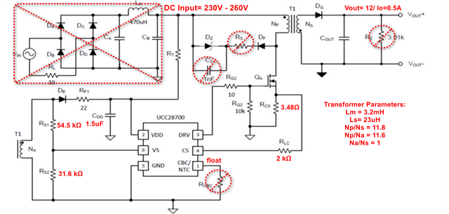
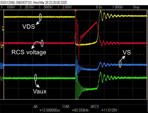
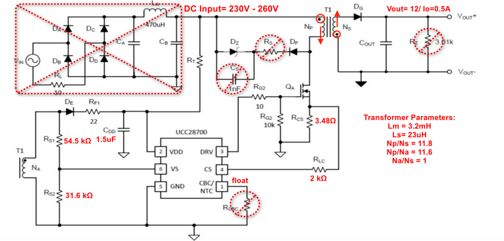
I have exactly the same issue with UCC28700Q1 as the one in this question "UCC28700-Q1: Need help reviewing the design including transformer", even the waveform are the same.
The part starts only giving 3 pulses and try to restart but then it goes off and then restart again. It's stuck at this stage and never startup the flyback correctly. Output voltage is 0V, the 3 pulses appear also at the secondary and auxiliary windings.
Unfortunately, the user asked about this issue didn't clarify how he solved this problem.
Can you please help?!

  • Hi Mohamed,

    Yes. That post fails to mention how the original issue was resolved 

    Have you looked at the VS pin during startup? Is it falling below UVLO or is the CS resistor too large making it believe it is hitting the current limit?

    I hope this gets you pointed in the right direction.

  • Hello,
    I have attached some measurements result from my circuit during the startup pulses that never help awakes the controller.
    Below, in Yellow is the VDS of the power FET, Blue is the VS voltage, and Green is the VGS of the power FET.

    Here is a zoom-in version>

    Since you suggested that the sense resistor might be too large (RCS= 3.65 Ohms according to Webench calculations). I attached below the voltage across the sense resistor, Yellow is the VDS of the power FET, Green is the VGS of the power FET and Blue is VCS across the sense resistor.

    I still have no idea why the controller is unable to startup the flyback! 

  • Are you trying to start up at full load or no load? If at full load, please try to reduce the load first.

  • I am testing at no load condition.
    Have you noticed any abnormal behavior in the attached measurement signals?

  • The gate pulse width has big mismatch with Vds pulse width. 

    Please read the following documentation for debug suggestions.

    https://www.ti.com/lit/an/sluaac5/sluaac5.pdf

    https://www.ti.com/lit/an/slua783/slua783.pdf

  • Hi Ning,
    I have tried most of the debug suggestions, still the converter is not able to start up.
    This is how my original schematic looked like:


    Here below what I tried:

    -  Increasing VDD capacitance from 1.5uF to 4.7uF and even 10uF --> even worse!
    -  Decreasing output capacitance --> didn't affect anything
    - Decreasing the resistor in-series with an auxiliary diode --> I removed the resistor RF1 (22 Ohms)

    Below I attach another oscilloscope measurements for VDS, VS, VCS, and Vaux voltages, in case it might give you any idea what would be the fault.

  • Hi Mohamed,

    Are you sure your schematics and/or turns ratios are correct? It looks like the winding on the Np and Ns are flipped:

    There is way too much ringing on the VD node and ideally, it would look more like this:

    The excessive ringing you are seeing is not at all normal. Can you confirm the schematic connections, transformer turns ratios, and polarity?

  • Also, is Rs a 0-ohm resistor? If Rs and Cs are not present, the voltage across the FET may cause damage. 

  • Hello JCHK;
    Sorry I pressed "This resolved my issue" by mistake.
    We still have the issue. 

    Regarding your question, yes we have a lot of ringing due to high leakage inductance of the transformer, I believe!

    Apart from the ringing, we didn't notice any damage in the FET since the VDS looks clean and seems that the current DZ snubber circuit is acting effectively to limit any spike on the FET drain.

    I need to confirm if the turns ratio NA/NS=1 is enough or not, because our targeted output voltage is 12V while the VDD has a minimum value more than this. Can you please confirm, maybe it's something wrong in the turns ratio of the auxiliary winding.

  • Hi Mohamed,

    The turns ratio might be wrong. The dots on the transformer are reversed in the schematic. Have you looked at what is happening on the VDD pin?

  • The dots in my circuit is the correct one, actually the schematic I am copying above is the schematic used by TI in their calculator tool for UCC28700, I just copied it as a reference only. I assure you that I have the correct polarity in my circuit.

    Regarding the VDD, I see a sawtooth shape for VDD trying to startup till 21V then it goes back to 8V in a triangular shape and that goes forever. The VDD never stabilizes. 
    The thing about the turns ratio of NA/NS= 1 might be the problem since my Vout=12V and if the auxiliary winding has the same number of turns it means that the steady-state VDD would also equal to 12V. Can you confirm if a steady-state value of VDD= 12 is enough or it will trigger the UVLO because the VDD has to be always higher than 21V "what's called VDD(ON)" in the datasheet!

  • Hi Mohamed,

    A steady state value of 12V will keep it running once it is already switching.

    If you see it falling to 8V, then you are likely falling below the VDD turn-off threshold. I noticed that your VDD capacitance is a little higher than what is recommended did you use equation 13 (page 19 of the datasheet) to derive this?

    In your schematic above, COUT is not shown.

    The UCC28700 was designed to run with much higher nominal voltage than 12V, Have you tried raising this to improve the headroom?