This thread has been locked.

If you have a related question, please click the "Ask a related question" button in the top right corner. The newly created question will be automatically linked to this question.

TPS62816-Q1: BUCK Divider resistor location question

Part Number: TPS62816-Q1
Other Parts Discussed in Thread: TPS54618C-Q1

Tool/software:

Hello sir,

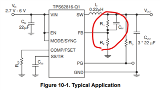
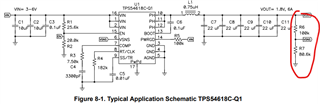
here is an question would like to discuss with you. From TI datasheet,  FB resistor place location is different, TPS62816-Q1 divider resistor is in front of output capacitor, the  other BUCK TPS54618c-Q1 divider resistor is difference location which is in back of output capacitor. Which one is correct? What's the difference function?

TPS54618C-Q1Automotive 2.95-V to 6-V, 6-A, Synchronous Buck Converter datasheet (Rev. A)

TPS62816-Q1 2.7-V to 6-V, 6-A Automotive Step-Down Converter in 3-mm × 2-mm QFN Package with Wettable Flanks datasheet (Rev. A)

  • Hi ,

    It is good to populate resistor divider close to IC for sync. buck converter and feedback signal connected to output capacitor with small routing to get best results.

    Both device shows different way of schematic but overall it convey the similar way of  connection.

    You have to check the layout for actual placement of the components and both devices follow similar layout where the resistor divider close to feedback pin of IC and feedback path is connected to output capacitor with small routing. 

    Best regards,

    Tanvee