This thread has been locked.

If you have a related question, please click the "Ask a related question" button in the top right corner. The newly created question will be automatically linked to this question.

UCC28881: Quiescent Power Consumption

Part Number: UCC28881
Other Parts Discussed in Thread: UCC28730, PMP22557

Tool/software:

Hi Team,

Customer ask whether this 18mW/9mW is IC total power consumption from supply end, and whether it has drive signal during this time. Could you please help check it? Thanks.

BRs,

Francis

  • Hi Francis,

    This is the IC power consumption while operating. This graph shows an example of the total load consumption compared to what the UCC28881 is consuming:

    This is an understated feature of this device as it has one of the lowest standby power ratings!

    I hope this answers your question.

  • Hi JCHK,

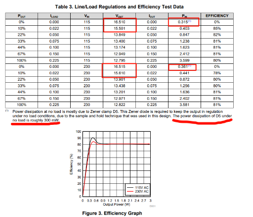
    Customer ask another question that why Vout will rise to 16.5V during no-load condition? It is from EVM user's guide.

    BRs,

    Francis

  • Francis,

    This is because the controller has min Ton and max Toff, as indicated in the datasheet. Unless the fault is triggered, the energy transfer from the primary to the secondary is not zero. So at no load condition, Vout gradually increases until the D5 burns all the energy.

    Best,

    Ning

  • Hi Ning,

    Seems the 300mW power consumption is must for this device? Even use a dummy load. Is there any way to design it and control <30mW power consumption under no-load condition? 

    This supply is Battery, so the quiescent power consumption is important.

    BRs,

    Francis

  • Not that I can think of with UCC28881. You can try UCC28730 for <30mW stand by power.

  • Is it necessary to add the voltage regulator D5? If it is not added, will the voltage rise indefinitely? Or will it eventually stabilize at a relatively large value? In other words, if I add a dummy load to my output, can I remove the voltage regulator? If so, how large should the load be? Is it okay within 50mW?

  • Hi Francis,

    Yes. D5 it is required to clamp the output voltage from rising. I am checking into this to see if there is a lower power consumption means of solving this with the UCC28881. Until then, the best recommendation is the UCC28730. PMP22557 is an example of using this as a high-side buck with less than 30mW of standby. 

    Let me know what you think.

  • Hi JCHK,

    How does 47mW come from? Irun current? The supply current.

    BRs,

    Francis

  • Hi Francis,

    A portion of this could be the leakage of C3. According to the datasheet. the leakage can be as high as 364uA. 

    Regards,

    John

  • The reference design of PMP22557 is 50V-150Vdc. I see that the IC used can reach 700V, right? Then can we use the reference design of PM22557 for our 300V solution? In the reference design, the no-load power consumption of 150V is 45mW. In the case of 300V input, will this no-load power consumption continue to increase? Can it meet our 50mV requirement? Can you help test the no-load power consumption of PMP22557 at the three points of 200V/250V/300V input voltage?

  • Hi John,

    Could you please help check above question for customer? uA current is difficult for both customer and field team to do test.

    And if the power loss if form leakage current of C3, what about the supply current, what are their respective proportions for 45mW power loss under no-load condition?

    BRs,

    Francis

  • Hi Francis,

    Can you submit a PDS request to see if they can test the leakage of PMP22557 at 200V, 250V, and 300V?

  • Hi Francis,

    While the UCC28730 is 700V tolerant the primary switch FET used in PMP22557 is not. This is only rated to 200V so would have to be switched out for another higher voltage FET.

  • Hi John,

    I have created the PDS request PDS-6710, please help apply it internally, thanks.

    And what about below question?

    "

    And if the power loss if form leakage current of C3, what about the supply current, what are their respective proportions for 45mW power loss under no-load condition?"

    BRs,

    Francis

  • HI Francis,

    The total leakage will be a function of the actual components used in the design. To know the respective proportions, you would have to measure the leakage paths on the board. 

  • Hi John,

    I would like to continue this online discussion.

    Do you know MPS MP182, it said that can achieve 5mW power loss in sleep mode.

    BRs,

    Francis

  • HI Francis,

    I am not able to find the datasheet of the MPS MP182. For low standby power our best solution is the UCC28730. The EVM for this consumes ~3.5mW of mW of standby power.