This thread has been locked.

If you have a related question, please click the "Ask a related question" button in the top right corner. The newly created question will be automatically linked to this question.

BQ24610EVM: Not Working

Part Number: BQ24610EVM

Tool/software:

Hello E2E Experts,

Good day.

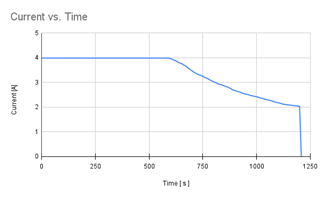
I was conducting tests for charging batteries, and at first, only the ACDRV, CE, and PG LEDs were lit (without the batteries connected). However, when we connected the batteries, all the LEDs turned off, and no current flowed. Despite this, the battery's output voltage remained correctly regulated at 21V, as expected from the board.

While we were continuing our tests, the output voltage suddenly stopped being regulated—it matched the input voltage from the power supply—and all the LEDs turned off. Since then, they have not turned back on. At the moment the issue occurred, the power supply was set to 24V, with the current limit configured to a maximum of 4A as a precaution.

Currently, the jumper settings are as follows:

  • JP1: LOW
  • JP2: ON
  • JP3: VREF
  • JP4: ON
  • JP5: ON

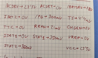
Regarding the pin readings, when connecting the power supply at 24V, the measured values for each pin are attached in the provided image.

Regards,

TICSC

  • Hello TICSC,

    Do you have a 10kohm resistor between TS ang GND?

    The TS pin requires an external thermistor to begin charging. If you do not have a an external thermistor, you can use a 10kohm resistor between GND an TS.

    Best Regards,

    Christian.

  • Hello Christian,

    Good day.

    I've checked what you mentioned, but it didn’t work. I measured the voltage drop across the 10K resistor, and it’s approximately 10 mV. Also, no LEDs are turning on, and with the power supply at 24V, the output to the battery is around 23.2V, which suggests that the voltage regulation isn’t working properly.
    Regards,
    TICSC
  • Hello TI-CSC,

    However, when we connected the batteries, all the LEDs turned off, and no current flowed. Despite this, the battery's output voltage remained correctly regulated at 21V, as expected from the board.

    If you remove the batteries, do the LED'S turn on?

    Best Regards,

    Christian

  • Hello Christian,

    When we remove the battery, the LEDs do turn on. Specifically, the ACDRV, CE, PG, and STAT1 LEDs light up.

    Please let me know if you need any further details.

    Regards,

    TICSC

  • Hello TI-CSC,

    What is the voltage of the battery you are connecting? Have you tried a battery with lower voltage. For example 15-18V?

    Best Regards,

    Christian

  • Hello Christian,

    Good day.

    The battery I’ve been using for the tests — and which matches the type we intend to charge — is a 6S LiPo battery, meaning it shouldn’t drop below 18V. At the moment, it’s charged to around 20V.
    Would you recommend using one with a lower voltage instead?

    I have another question regarding what you've recommended me in the last email. Since the battery supply voltage of the board is around 21V, is it safe to connect a battery to charge that is between 15 and 18V? Does the board adjust the voltage itself?

    Regards,

    TICSC

  • Hello TI CSC,

    Would you recommend using one with a lower voltage instead?

    I'm using a EVM and I don't see this issue with 20V battery, so 20V battery should be okay.

    I have another question regarding what you've recommended me in the last email. Since the battery supply voltage of the board is around 21V, is it safe to connect a battery to charge that is between 15 and 18V? Does the board adjust the voltage itself?

    No, the board does not automatically adjust the voltage, you will need to change the resistor on VFB.

    Have you tried using a bidirectional power supply, to confirm the issue is not the battery?

    Can you provide images of your testsetup?

    Best regards,

    Christian.

  • Hello Christian,

    Good day.

    I’m attaching a picture of the current setup.

    I haven’t had the chance to try using a battery with a lower voltage yet, but I’ll do so as soon as I can. The challenge is that I need to charge 6-cell LiPo batteries.

    After adjusting the resistors on TS, the LEDs now turn on as shown in the picture. However, the issue now is that the output is not being regulated to 21 V, even though the input is 24 V.

    Regards,

    TICSC

  • Hello TICSC,

    However, the issue now is that the output is not being regulated to 21 V, even though the input is 24 V.

    I assume this is when the battery is connected? It should be regulated to 21V when battery is disconnected. However when battery is connected, the measured voltage should be what the actual battery voltage is. It should be able to charge up to the programmed 21V, are you not seeing this? Is charge stopping before it reaches 21V?

    Best Regards,

    Christian.

  • Hello Christian,

    Good day.

    To clarify, the behavior I observed was with the battery connected. With a 24V input, the output voltage follows the battery voltage, but the charge does not stop at the programmed 21V — it continues rising until the difference between the input and battery voltage is about 1V.

    Additionally, the battery voltage increases very quickly during charging, which makes me question whether the charging process is being properly regulated.

    Regards,

    TICSC

  • Hello TI-CSC,

    To clarify, the behavior I observed was with the battery connected. With a 24V input, the output voltage follows the battery voltage,

    This is expected.

    With a 24V input, the output voltage follows the battery voltage, but the charge does not stop at the programmed 21V — it continues rising until the difference between the input and battery voltage is about 1V.

    I'm not seeing this behavior in the lab.

    Did you change the VFB resistor divder?

    Where are you measuring the voltage greater than 21V? is this at the battery or at output terminal?

    What are you using to measure this voltage?

    How accurate is this voltage measurement?

    Have you tried using a bidirectional power supply to confirm issue is not the battery?

    Additionally, the battery voltage increases very quickly during charging, which makes me question whether the charging process is being properly regulated.

    The best way to evaluate this is to capture the charge profile. Typically the voltage increases quickly during trickle charge and prechare state.

    Best Regards.

    Christian.

  • Hello Christian,

    Good day.

    Regarding the VFB resistor divider, I haven’t made any changes to it yet, mainly because I’m not sure what value it should be changed to. Should I try replacing it with another of the same value just to check if the issue lies there, or is it a matter of modifying its value?

    Concerning the voltage measurements above 21V, I am using a device that measures both voltage and current, and it is placed between the battery and the board. I have also verified the voltage using a voltmeter directly at the charger’s output terminal, and the readings are consistent with what the other device reports.

    As far as I can tell, the measurement equipment is accurate, and any error should be practically negligible.

    I haven’t tested the setup with a bidirectional power supply, but I have used multiple different batteries, and the issue persists in all cases. This leads me to believe the battery is not the root cause.

    I haven’t yet captured a full charge profile, but I’ll try to do that soon and will share it with you once available.

    Please let me know if there’s anything else I should check or try.

    Regards, 

    TICSC

  • Hello Christian,

    I have recorded the charge profile of the battery. I’m attaching the corresponding graphs so you can review the charging behavior visually. I’ve also included the raw data tables in case you would like to analyze the values more closely.

    Please let me know if you notice anything unusual or if you have any suggestions based on the results.

    Battery_Test_Data.pdf

    Regards,

    TICSC

  • Hello TI CSC,

    Should I try replacing it with another of the same value just to check if the issue lies there, or is it a matter of modifying its value?

    This might help. R25=909k, R28=100k

    What is the VFB voltage when the battery reaches the max charge voltage?

    Best Regards,

    Christian.