Tool/software:
Hi,
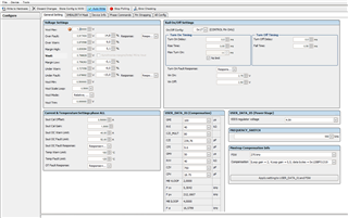
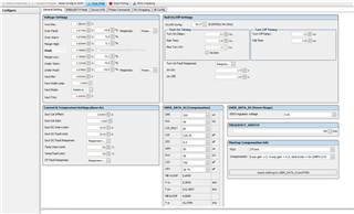
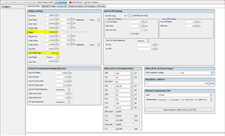
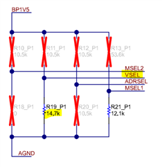
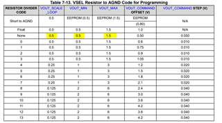
How we could change the Vout on the evaluation board? Is it possible or i have to manually change the resistor? if yes which resistor?
Also for our design do we always need to relay on the divider resistor at VSEL? I thought by default it will be the divider resistors and afterwords we could change the voltage out as per our desire using PMBUS?
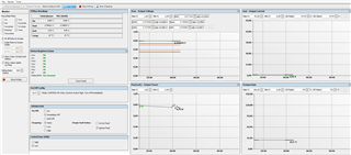
The IC gives the temperature value using PMBUS is the value given is self heating or its the total ambient+self heating temperature? how to calculate it?
Where to find the relationship between frequency and self-heating of the IC? i want to see the trade off of frequency vs Temperature as my applications ambient temperature is 100°C in average
Thanks
Sal