A related question is a question created from another question. When the related question is created, it will be automatically linked to the original question.
If you have a related question, please click the "Ask a related question" button in the top right corner. The newly created question will be automatically linked to this question.
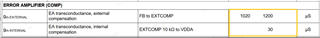
1. The gm spec is given in us, which is the same units as uA/V.
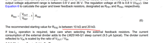
2. 10-20k is a good region to start with to have a feedback network with large enough resistance to not draw much current from VOUT, but not too large to cause issues with regulation.
Actually, the transconductance is given in units of µS (uppercase S for Siemens), not µs (lowercase s for time).
And 10-20kΩ is a good starting point for the lower feedback resistor, as less than 5kΩ will result in the IC detecting FB as low at startup and setting a fixed 5V output. See the data sheet for guidance on this.
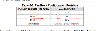
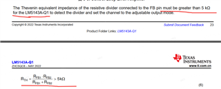
What you have copied above are values for fixed output settings. Looks like there are no limits on the feedback resistances for an adjustable output voltage setting (unlike the LM25141 and LM25143, for example). As Dino mentioned, 10-20kΩ is good from a quiescent current standpoint. Higher than than is fine as well, as long as the upper resistor doesn't exceed ~200kΩ (at which point its impedance becomes unnecessarily high, thus increasing noise sensitivity, possibility of board contaminants affecting the behavior, etc.)
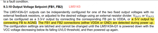
For the LM5143,if FB is connecting to gnd ,the output is 5V。In this spec,recommend RFB1//RFB2<5kΩ,but not only RFB2 <5kΩ,why that?Could it be that the low mos is open at the IC power up?
The LM5143 is a different controller (not relevant to the LM25148) - apologies for the confusion by mentioning that.
The LM5143 needs to see more than 5kΩ on FB, otherwise it will detect it as being low and set a fixed 5V output. The LM25148 does not have that concern, as the fixed output setting is determined only by a resistor to VDDA.