This thread has been locked.

If you have a related question, please click the "Ask a related question" button in the top right corner. The newly created question will be automatically linked to this question.

TPS25750: TPS25750 software

Part Number: TPS25750
Other Parts Discussed in Thread: TPS25751,

Tool/software:

Hi team,

My customers Sercomm are using TPS25750 in Set-top-box project and want to ask one question. TPS25750 is communicate with CPU through I2C, do we have some drive code or sample code that can share to customers?

Thank you!

Regards,

Maggie

  • Hi Maggie,

    We do not have a driver or sample code for generic I2C communication. All we offer is the TRM with the register mapping.

    If this is not a continuation of a previous project, we highly recommend that they use the TPS25751 in instead of the PTS25750. The TPS25751 is NRND, and the TPS25751 is the direct p2p successor part.

    If they are looking into the "flashing over I2C" process, there is a flowchart in the TRM that describes the programming sequence. For generic I2C reads and writes from the registers, the TRM is what is available.

    Thanks and Regards,

    Chris

  • Hi Chris,

    Thank you for your reply. 

    Currently customers are using the old version schematic to build product samples and will move to TPS25751 in next version PCB. I have two questions that would like to ask:

    1. I didn't find the TRM of TPS25750, and the datasheet of TPS25750 doesn't include the resister map introduction like what in the TRM of TPS25751. Could you kindly help provide the TRM or register map of TPS25750? Is it the same as 25751?

    2. Customers choose 'AlwaysEnableSink' mode through hardware, will TPS25750 automatically match the voltage according to the ADC value of the input voltage?

    Thank you!

    Regards,

    Maggie

  • Hi Maggie,

    1. I didn't find the TRM of TPS25750, and the datasheet of TPS25750 doesn't include the resister map introduction like what in the TRM of TPS25751. Could you kindly help provide the TRM or register map of TPS25750? Is it the same as 25751?

    Yes, it should be very similar to the tps25751. If they plan on moving to the TPS25751 eventually, it should be fine for them to reference the TRM. All of the major fields should be the same. There might be some new fields in the TPS25751 TRM due to it being a newer part, (things like liquid detection for example were only introduced with the TPS25751), but many of the core registers (Port Control, Port Config, Status registers, TX source and sink) should be the same.

    2. Customers choose 'AlwaysEnableSink' mode through hardware, will TPS25750 automatically match the voltage according to the ADC value of the input voltage?

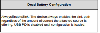
    Always enable sink is a "dead battery configuration", which is the PD controllers behavior there is no power and it draws power from the Type-C port.

    The device will advertise a USB-C sink termination, but will not enter PD. This means it will only negotiate the default 5-V type-c contract.

    Thanks and Regards,

    Chris

  • Hi Chris,

    Thank you for your reply!

    Since we don't have the drive code for customers, could you kindly help guide how to configure the register if customers wan to get a input of 20V/3A? I'm not familiar with PD so please kindly help me here Thanks a lot!!

    Regards,

    Maggie

  • Hi Maggie,

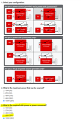
    Device configuration is done through the App Config GUI. The GUI can be accessed from the product page.

    Once in the GUI, the customer can select the configuration they want, and question 3 is where they can choose their required sink power.

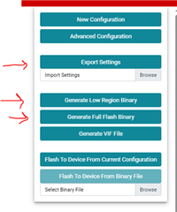
    Once the gui questionnaire has been filled out, they can generate a fw image "binary" file, that can be loaded to the EEPROM or MCU that is used to load the image to the PD controller on boot. They can save their product settings with the "Export Settings" option.

    The TPS25751 does use an updated GUI, so the project they make here will not port directly over. It does have very similar questions so replicating it should not be  difficult when they do move.

    I would recommend they move sooner rather than later to reduce repeated efforts.

    Thanks and Regards,

    Chris

  • Hi Chris,

    Thank you for your suggestion!

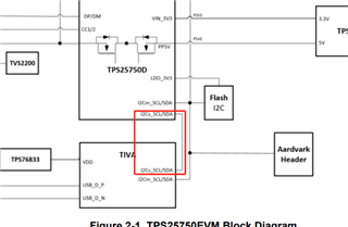
    The method you mentioned is to use the pd controller as the master device to access the eeprom, which is not the same with customers' design. I would like to ask if the public board can switch to the i2c line shown in the figure below to configure the pd controller?

    Thanks again!

    Regards,

    Maggie

  • Hi Maggie,

    Unfortunately the EVM does not support MCU I2C flashing through the TIVA. The EVM only supports the EEPROM config. If the customer decides to do MCU patch loading, they can use the same .json and generate the low region .c file to use with their MCU.

    Thanks and Regards,

    Chris

  • The TPS25750EVM does not support MCU I2C flashing through the TIVA and only supports the EEPROM config. But according to previous communication, I thought that only after the system is fully up, the CPU can start the negotiation of 20V voltage by writing values ​​to the corresponding registers of the PD through I2C. So I’d like to ask some questions:

    1. Which registers should be written and what values ​​should be written?
    2. The original idea was to put the PD code in the eMMC, and the CPU read the PD code in the eMMC, and then inject it into the PD through I2C to achieve the negotiation of 20V voltage.
      1. Does TI have source code to provide?
      2. What is the code in the EEPROM?
      3. Can the method described be implemented? If so, is the code stored in the eMMC the same as the code in the EEPROM?
    3. In the hardware design, the ADCIN1 and ADCIN2 pins are configured as always enable sink mode according to the reference design. Will this affect the subsequent negotiation and activation of the 20V voltage? Could you kindly help to confirm this again?
  • Hi Maggie,

    Let me clarify some behaviors first.

    The TPS2575x family of parts has rom and ram internal to the device. On power up, it is required that an external source loads a "patch bundle" to the ram. It is never recommended to run only from the rom. The patch bundle can be loaded either from an EEPROM (the PD controller checks for an I2C EEPROM and attempts to load the image) or an I2C controller device needs to load the patch bundle using the PBMx flow.

    The patch bundle is a binary file that contains (1) device configuration information and (2) patches. The patch bundle is generated using the App Config GUI tool. For the EEPROM potion, you need to generate the "Full Flash Binary" and for the MCU you use the "low region binary". They are essentially the same thing, just the full flash has two copies of the low region image for backup purposes.

    On bootup, once the patch bundle has been loaded, registers can be changed over I2C to change some behavior of the PD controller.

    The TPS25750EVM does not support MCU I2C flashing through the TIVA and only supports the EEPROM config.

    This is still correct, the TIVA does not support MCU I2C flashing. They can hook up their own MCU to the I2C lines if they want, but the board does not support I2C controller patch bundle loading by itself.

    But according to previous communication, I thought that only after the system is fully up, the CPU can start the negotiation of 20V voltage by writing values ​​to the corresponding registers of the PD through I2C.

    Sortof correct. For I2C writes to happen, a patch bundle needs to be loaded. As mentioned above, this can happen through EEPROM or I2C controller.

    Which registers should be written and what values ​​should be written?

    This depends on your initial configuration. Typically to change the advertised/negotiated voltage, you will update the Transmit Source (0x32) or Transmit Sink (0x33) register and add or remove the PDO that you want. Then to renegotiate the contract with the updated voltages, you need to use the "SSrc" (for new source ,contract) or "GSrc" (for new sink contract). 

    They will need to update the PDOs which are formatted according to the PD spec. The values depend on the voltage, current, and type of PDO.

    The original idea was to put the PD code in the eMMC, and the CPU read the PD code in the eMMC, and then inject it into the PD through I2C to achieve the negotiation of 20V voltage.

    This can be done on their system. They can use their MCU to program the PD using PBMc and then read/write to register on I2C for additional config.

    Does TI have source code to provide?

    No, we do not have source code. The TRM's provide a flowchart for the PBMs process. (see section 5.2 of the TPS25751 TRM)

    • What is the code in the EEPROM?

    It is the patch bundle mentioned before. A binary image generated by the GUI that holds config and patch information.

    Can the method described be implemented? If so, is the code stored in the eMMC the same as the code in the EEPROM?

    Yes, this is the PBMx flow described in TRM section 5.2.

    In the hardware design, the ADCIN1 and ADCIN2 pins are configured as always enable sink mode according to the reference design. Will this affect the subsequent negotiation and activation of the 20V voltage? Could you kindly help to confirm this again?

    If you load the patch bundle correctly this should not affect the negotiation and activation.

    Thanks and Regards,

    Chris