This thread has been locked.

If you have a related question, please click the "Ask a related question" button in the top right corner. The newly created question will be automatically linked to this question.

UCC29002:Absolute maximum rating for the LS pin

Part Number: UCC29002

Tool/software:

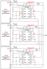
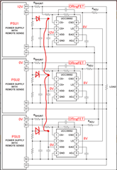
The configuration is to operate three PSUs in parallel, with each output connected via an ORingFET.
PSU1 may have an output voltage of 12V, while PSU2 and PSU3 may have an output voltage of 0V.
The LS pin is common to each UCC29002DR/1 and VLS = 8V.
PSU2 and PSU3 have VDD = 0V.
The absolute maximum rating for the LS pin of the UCC29002DR/1 is VLS = -0.3V to VDD. Is there any problem with using it this way?

  • HI Wada-san,

    Yes, the UCC29002 can work like this. Also, here is an application note (SLUA550) showing how with the Or-ing controller, the load sharing can be even more accurate at higher load currents.

    I hope this answers your question.

  • Hello Wada-san, 

    Aside from working with OR-ing FETs, I understand your question about the voltage rating of the LS pin when the VDD of their respective devices = 0V. 

    I suggest that there are 3 ways to avoid any overstress:

    1.  Connect VDD of each load-share controller to the output voltage bus after the OR-ing diodes.  This can work if at least one OR-ing FET is always on to provide ~12V to the load. 

    2.  Connect all three LS controllers to a common VDD-bus voltage source, derived from some other known power source or sources.  (This would be similar to suggestion #3.)

    3.  Connect the VDD of each LS controller to their respective input voltage rails through a diode and connect all three VDD's together.  The diodes will block reverse powering of PSUs that are off.   See this diagram: 

    Regards,
    Ulrich