This thread has been locked.

If you have a related question, please click the "Ask a related question" button in the top right corner. The newly created question will be automatically linked to this question.

LM5122-Q1: Question about LM5122-Q1

Part Number: LM5122-Q1

Tool/software:

Hello:

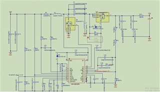
The above is the schematic diagram, and the following issues were encountered during use:

1. HO output waveform is very messy and not working properly

2. Without using HO to drive MOS synchronization, using diodes can work normally, but driving MOS synchronization does not work

3. Adjust the RT resistor and increase it to 36K. The switching frequency decreases and the heating is significantly reduced. However, after connecting the 390UF output capacitor, the output 75V voltage cannot be started. The resistor can only be started when it drops to 20K and outputs 75V

4. The inductance and MOS are heating up a bit severely when working with diodes without MOS synchronization

  • Hi Jimmy,

    Thanks for using the e2e forum.
    Based on the component placement, the HO connection looks okay.
    Can you please try the following adjustments:

    - Reduce C18 to 100nF. This cap should not be larger than the BST cap (C23)
    - Increase R6 resistance. E.g. 1k Ohm

    If the high side driver signal does not stabilize, it might be helpful to look into waveform signals to further analyze the behavior.

    Best regards,
    Niklas