Tool/software:
Hi Team,
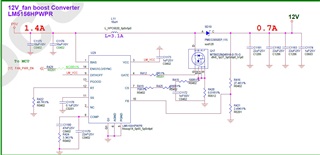
After our review, it seems to be okay, may we know if there any issue or modify to this schematic? thanks for your support and learn from you,

This thread has been locked.
If you have a related question, please click the "Ask a related question" button in the top right corner. The newly created question will be automatically linked to this question.
Tool/software:
Hi Team,
After our review, it seems to be okay, may we know if there any issue or modify to this schematic? thanks for your support and learn from you,

Hi Tommy,
Thanks for using the E2E forum.
I have reviewed your schematic and found some recommendations:
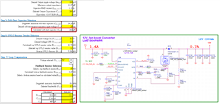
1. Kindly use the Quick start calculator to recalculate the Comp pin compensation.
2. Kindly, use the recommended soft start capacitor to mitigate the initial inrush currents caused by the output caps.
https://www.ti.com/tool/download/SNVC224
Best Regards,
Hassan
Hi Hassan,
This schematic diagram is designed based on the simulation results on the TI website.
It seems that there is some discrepancy with the numerical calculation suggestions for related components in Excel that you provided.
Which one should we focus on?
https://webench.ti.com/power-designer/switching-regulator/customize/11?VinMin=3.5&VinMax=6&O1V=12&O1I=0.7&base_pn=LM5156H&AppType=None&Flavor=none&op_TA=30&origin=pf_panel&lang_chosen=en-US&optfactor=3&Topology=Boost&flavor=none&VoltageOption=none
Hi Nicholas,
I recommend to use the Quick Start calculator because it design to focus the particular device.
Best Regards,
Hassan
Update the schematic according to the result of Quick Start calculator.
Then help confirm whether it is OK?

Hi Nicholas,
Can you please check the phase margin for the selected compensation network?
It should be greater than 60 degrees.
The SS is fine.
Best Regards,
Hassan