This thread has been locked.

If you have a related question, please click the "Ask a related question" button in the top right corner. The newly created question will be automatically linked to this question.

TPS63021: Enabling PS

Part Number: TPS63021
Other Parts Discussed in Thread: TPS631000, TPS631010, TPS63900

Tool/software:

Hi,

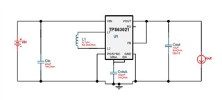
I am using TPS63021 converter for my application. I would like to use the TPS63021 in power-save mode. Is it better to design the PS/SYNC pin to connect to the GND via a resistor or directly to the GND? Also, the current consumed by the output side of the TPS63021 is approximately 25 μA, but when power-save mode was disabled, the TPS63021 itself consumed approximately 5 mA of current. If power-save mode is enabled, will the current consumed by the TPS63021 itself be approximately 25 μA of the static current during operation described in the data sheet?

  • Hi   Kimba,

    Recommend to connect PS pin to GND directly.

    I think you mean if the consumption of TPS63021 is 25uA or not when Iout is 25uA, right?  if so, the answer is no.  25uA quiescent current is measured without any switching, When load is exist, consumption of device itself will be higher one.

    Regards

    Tao

  • Hi Tao,

    I understood that the current consumption of TPS63021 itself is not 25 μA due to the load on TPS63021. Looking at the data sheet, the graph showing the relationship between the efficiency and the output current when PS is enabled(Figure10) shows that the efficiency is about 65% when the output current is 100 μA, so it can be estimated that it is about 60% when the output current is 25 μA. Based on this, is it correct to think that the current consumption of TPS63021 is 25 μA/60%=42 μA?

  • Hi  Kimba,

    Please use input power for current consumption calculation. since you have Vout and Iout, you can calculate the input power while assuming efficiency here is 60%( here, i think 50% is more resonable).

    Regards

    Tao

  • Hi,

    I have a different problem about TPS63021.

    When I connected PS pin to the GND, the VOUT in power saving mode reaches up to 3.58 V. As far as the data sheet is concerned, I thought the VOUT would go up to 3.5% at the maximum, but could it go up to 3.58 V because of the typ value? Or could the VOUT go up more depending on the design?

  • Hi  Kimba,

    3.58V you mentioned is the peak voltage or the DC one?

    3.5% is a typical value and also depend on your design. For example, with larger output capacitor, the peak voltage will be lower,

    Regards

    Tao

  • Hi Tao, 

    3.58V is the peak  voltage. 

    The output capacitors are equipped with 3 x 22 μF capacitors as in the recommended circuit, and one 0.1 μF capacitor closest to the IC.

  • Hi  Kimba,

    Got, 3.5% is a typical and ideal value of peak voltage in PFM mode, in most case, this peak should be higher than 3.5% because the delay of comparator internal. Vout is keep rising in this delay time.

    Regards

    Tao

  • Hi Tao,

    Thanks about the peak voltage.

    I am looking for a way to reduce the current consumption of the TPS63021 in power save mode as much as possible. For example, is it safe to use an inductor coil of 4.7 μH? I was looking at Webench Power Designer and found a circuit using a coil of 4.7 μH.


    If there are other measures to reduce the current consumption, could you please let me know?

  • Hi  Kimba,

    4.7uH should not be a good option if you have PWM mode over your actual load. Because it will  obviously reduce frequency of RHPZ and may cause unexpected instable loop.

    From other side, change inductor to 4.7uH may not work to improve efficiency over your load. Especially when you load is ultra light, then quiescent is main part of consumption.

    If possible, i think swap to our new BUBO device should be a goog idea, such as TPS63900,TPS631000, TPS631010/1. Their quiescent current is much lower.

    Regards

    Tao

  • Thanks Tao,

    Our highest IOUT is 10mA so we would not be using PWM mode. If so, would it not be much of a problem?

    The converter itself is consuming between 25 to 50 μA due to switching and I would like to stabilize this as much as possible.

    It's difficult to choose a different IC in this case.

  • Hi Kimba,

    Got it, since maximum load is 10mA, then i think you are free to change the inductor if you want.

    Regards

    Tao