


Tool/software:
Hi Team,
we are currently designing with the LM5050, and testing has found that when the load is powered by an extra voltage, once our product is switched off, The GATE of the LM5050 has a signal
As shown in the figure below
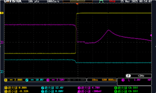
The CH1 is the output current of our power modules, and the current probe is oriented toward the module end.
The CH2 is the load voltage, there is an external 10V supply, and our module output voltage is 12V
CH3 is the Vgs of LM5050
Once the power module is turned off, Ch1 does not have a current in or out power module, why does the LM5050 introduce a GATE signal?
