This thread has been locked.

If you have a related question, please click the "Ask a related question" button in the top right corner. The newly created question will be automatically linked to this question.

TPS25763Q1EVM: Questions about development board operation and GUI configuration.

Part Number: TPS25763Q1EVM
Other Parts Discussed in Thread: TUSB1064, TPS25763-Q1

Tool/software:

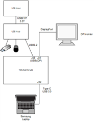
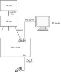
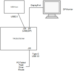
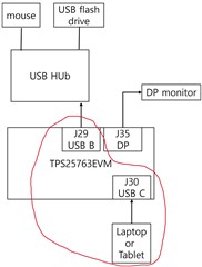
I purchased the TPS25763Q1EVM for testing, but I encountered some issues.
I am conducting tests for USB data communication and DP Alt Mode.
After purchasing the development board, does USB data communication and DP Alt Mode not work without performing any software configuration?

Also, the development board states that a DC power input of 5.5V to 18V is required, but PD charging does not work properly at voltages below 12V.
Is this also something that needs to be addressed through software configuration?

If software configuration is necessary, could you provide a basic configuration file for fundamental operations?

I look forward to your response.

Thank you.

  • Hi Bongeon,

    The board comes preinstalled with firmware that will provide 60W at 12V.  There is a input voltage foldback threshold that will result in the controller only advertising 36W.  But if input voltage at the 763 pin is >11.76V, this should not be an issue.

    For USB data, ensure J18 is in the OPEN position.  I ran a quick sanity check on the stock configuration and it is working.  What is it that you are connecting to the port?

    Full details for the hardware are available in the EVM user's guide.https://www.ti.com/lit/pdf/slvucs2

    Details for using the GUI for future software configuration is also available via a user's guide.  You shouldn't need to do anything if the board is stock out of box, though.  https://www.ti.com/lit/pdf/slvubx5

    Regards,
    Eric

  • Hi Eric,

    I tested it by connecting to the USB-C port of a Samsung laptop. I confirmed that the external monitor displayed correctly by using the HDMI port of the Belkin USB-C multi-hub or by connecting a USB-C to HDMI cable to the USB-C port of the laptop.

    Currently, when I connect the TPS25763Q1EVM to the laptop and supply power, the charging function works properly. However, external monitor output through the DP port and USB data communication through the J29 connector are not functioning.

    For USB data communication, I tested it by connecting a USB hub to the J29 connector. The J18 connector is in the OPEN position. I have not changed the connectors from their default state as shipped.

    Thank you.
    Bongeon

  • Hi Bongeon,

    I am still looking into this but haven't had a chance to test on my end today.  My takeaway is you know the laptop and monitor are working when 763Q1EVM is not involved.  But when you introduce the EVM to the setup, neither data nor video work.

    One quick thing to try - are you certain the type-c cable is fully featured?  That is, do you know that all the TX/RX pairs are present in your cable?

    If you have a PD analyzer such as this one from TotalPhase, are you able to log the CC traffic and share the log?
    https://www.totalphase.com/usb-power-delivery-analyzer-end-of-life/

    Thanks,
    Eric

  • Hi Eric,

    I'm sorry for the late reply. I went on vacation, so I conducted the test later than planned.
    Following your advice, I rechecked the C-to-C cable and confirmed that the display output is working. Thank you.

    However, I encountered an issue where display output and data communication do not occur simultaneously.
    When measuring J2, J20, and J22, I obtained the following readings (using a multimeter, and the H state measured around 3.5V): (CTL1: H, CTL0: L, FLIP: H or L).
    According to the TUSB1064, this state is recognized as 4Lane DP. How can I get the TUSB1064 to operate in the One Port USB 3.1 + 2 Lane DP state?

    Thanks,
    Bongeon

  • Hi Bongeon,

    One item of clarification.  You should still be able to get USB2.0 data regardless of the TUSB1064 settings.  The D+/D- signals do not get MUXed.  I am aware of USB3.x failures on the EVM (board/system level, not silicon) that I am debugging.  If you only need USB2.0 data, you can use a standard USB A-B cable at J29. 

    The USB3/DP lanes are configured based on the PD negotiation between TPS25763-Q1 and the sink PD controller.  763 takes the PD negotiation and translates that into CTL0, CTL1, and FLIP GPIO states.  If you want to brute force override these settings, you can do so by removing the CTL0 jumper from J22 and manually shorting the center pin of the header to either LDO3V3 (logic high) or GND (logic low) prior to sink attach.  However, this will not necessarily result in success since the PD sink device is blind to the fact the MUX settings were manually overridden.

    Are you able to capture PD traffic via an analyzer such as the one I linked above?  This will shed light on what conditions the 763-Q1 and PD sink device negotiate.

    Regards,
    Eric

  • Hi Eric,

    We do not have a PD analyzer at the moment, so we are unable to capture PD traffic. We have purchased a CY4500 PD analyzer and are currently waiting for it to be delivered.

    In the meantime, we’ve conducted a few more experiments, and here is the current status:

    First, we tested by connecting the USB-C port of a Samsung laptop to J30. Charging and DP output both worked normally. We also confirmed that the USB hub connected to J29 was functioning by connecting a mouse and a USB flash drive. Although we used a USB 3.0 cable for the J29 connection, the USB flash drive operated at USB 2.0 speed, and CTL0 remained in the low state. We saw the same behavior even when using a USB 2.0 cable, as you mentioned. When we manually forced the middle pin of J22 to logic high, neither the DP output nor the USB hub functioned.

    After testing with the Samsung laptop, we moved on to our original target device—a tablet PC (Galaxy Tab Active 4 Pro)—and tested it with the EVM. When the tablet was connected to J30, LED D1 blinked a few times and then the tablet displayed the messages “USB connector connected” and “USB connector disconnected” repeatedly. After that, connecting the DP connector successfully displayed on an external monitor. However, in cases where D1 did not blink during the connection, the external monitor connection via the DP connector failed. In such cases, reconnecting J30 or powering off the external power supply and waiting 20–30 seconds before reconnecting allowed the external monitor to work again via the DP connector.

    When the external monitor was successfully connected, the signal levels remained the same as before (CTL1: H, CTL0: L, FLIP: H or L). However, USB 2.0 data communication through J29 did not work in this state. Connecting a USB hub or directly connecting a mouse to J29 (using a USB male B to female A connector) had no effect.

    Additionally, when USB 2.0 communication worked without the DP connector attached, connecting the DP cable afterward did not allow the external monitor to be recognized.

    Would it be possible for you to suggest any solutions or ideas to address this situation?
    We understand that waiting for the PD analyzer and running tests with it may help resolve the issue, but we’d like to try as many approaches as possible in the meantime.

    Thank you,
    Bongeon

  • Hi Bongeon,

    I'm not sure I understand all your setups.  I've tried to visualize them below.

    Everything above sounds like it works.  Laptop video output is mirrored to monitor and hub is proven to be working via mouse, USB flash drive.  Did you then move the flash drive to J30?  This is where I'm confused.

    It sounds like if/when the flash drive is connected to J30 it works at USB2.0 speed.  Is the connection from the USB host to hub 2.0?  Or is the hub not 3.0 capable?  This could explain the bottleneck.  If the flash drive is not moved to J30, 763EVM has no effect on it's operation.

    When we manually forced the middle pin of J22 to logic high, neither the DP output nor the USB hub functioned.

    This is probably because the sink is configured to output 4 lane DP, as negotiated over PD.  This is what I meant when I said "this will not necessarily result in success since the PD sink device is blind to the fact the MUX settings were manually overridden."

    When the tablet was connected to J30, LED D1 blinked a few times and then the tablet displayed the messages “USB connector connected” and “USB connector disconnected” repeatedly

    It's hard to tell what's happening here without a PD log.  One easy thing to verify is if the power supply to the EVM is capable of providing the power required to charge the tablet.  That is, is input supply browning out, causing the port to reset?

    The item I'm most curious about is what happens in the following configuration:


    Thanks,
    Eric

  • I apologize for not explaining my experiment clearly earlier.

    I conducted the experiment as shown in the diagram. I connected a laptop or tablet to J30, and a USB hub to J29. For all tests, I used a USB 3.2-compatible cable between J30 and the host device. I believe the part marked in red is the host side of the hub—am I correct in thinking this?

    When connecting the hub directly to the laptop and then plugging a flash drive into the hub, it operates at USB 3.0 speed as expected. However, when the 763EVM is inserted between them as shown in the original diagram, the flash drive only operates at USB 2.0 speed. I tested this using both USB 2.0 and USB 3.0 cables between J29 and the hub, but the speed remained at USB 2.0. Also, CTL0 remained in the low state.

    When using a tablet, if the DP monitor output works, the USB hub does not function. Conversely, when the USB hub works, the DP monitor does not output anything.

    Regarding the D1 blinking issue: I'm powering the EVM using an external power supply rated at 5A, so I believe power insufficiency is not the cause. I think we’ll be able to determine the exact issue once the PD analyzer arrives and we can check the logs.

    P.S. Please let me know if my assumption is correct—that the part marked in red in the diagram is acting as the USB host.

  • Hi Bongeon,

    J29 is UFP only, which is why it uses Type B connector instead of Type-A. 763EVM does not support data path where J30 is UFP, J29 is DFP.  An upstream host is expected to connect to J29.  I.e a vehicle's SOC.

    Regards,
    Eric

  • Hi Eric,

    I understand that the 763EVM is intended to operate as shown in the first diagram from your comment.

    In my case, I am developing a new board where the laptop or tablet acts as the USB host, as shown in the first diagram from my previous comment. To support this design, I have been using the 763EVM for testing, with the goal of using it as a reference.

    According to the product details for the TPS25763-Q1, the "Data Role" is listed as DRD (Dual Role Data).
    If I want to use J30 as the UFP and J29 as the DFP on the EVM, what steps would I need to take to achieve that?

    Thanks,
    Bongeon

  • Hi Bongeon,

    Good point.  For USB2.0, theoretically things should work fine.  I am not certain the USB MUX can handle the opposite data path.  I have a meeting scheduled for Wednesday with the MUX product line and will be sure to clarify this point.

    Regards,
    Eric