This thread has been locked.

If you have a related question, please click the "Ask a related question" button in the top right corner. The newly created question will be automatically linked to this question.

TPS25751: Patch loading with Teensy 4.1

Part Number: TPS25751

Tool/software:

Hi everyone,

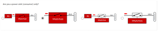
I am trying to load a patch file to TPS25751D. My use case is power sink(consumer) only. I attached the config file.

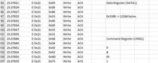
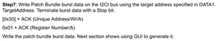
The problem is I am sending the patch data with 32 byte transmissions.I am using a teensy 4.1. In the end I get no I2C errors but device is stuck in PTCH mode. Can you help me solve the issue?

I have attached the I2C log file, patch data, and the code.

USBPD_flash.cppcapture.txttps25751.h

Kind regards.

-Sukru

  • Hi Chris,

    Thank you for your reply! I fixed the error regarding patch size but still it doesn't work. I also added boot flag check in the beginning and I am getting similar results like yourself. I realized that after sending the patch and sending PMBc command, DATA1 register is showing "not a patch" and "failure" output by reading 0x00 0x00 0x40 0x80. I attached the new log and my desired config. I want to see 20V output.

     capture_new.txt

  • Hi Chris, an update

    I successfully transitioned to APP mode. I am transmitting an additional 0x01 before transmitting the patch file. Now I am in APP mode but I still don't see the output. Do you have any idea?

    app_mode.txt

  • Hi Sukru,

    Chris S. is OoO and will be returning tomorrow.

    What do you mean by "transmitting an additional 0x01"?

    When you send the bursts, could you try sending them in 64 Byte bursts instead of 32?

    Thanks and Regards,

    Chris

  • Hi Chris,

    This is the additional 0x01 i have been transmitting but i noticed configuration already has this. I successfully changed from PTCH to APP mode after removing it. However, my problem still continues as I cannot see 20V output. I have one more question:

    After switching to APP mode I realized that the chip is in dead battery mode and powered by VBUS. At that point I am unable to see 20V output with this configuration:
      

    I cleared the register by executing DBfg command. Now the chip is powered by VIN_3V3 but in the design VIN_3V3 is not connected.

    Can i use the selected power sink configuration without connecting VIN_3V3? I thought since the chip is already powered on and there is a successful I2C communication just by using VBUS,  VIN_3V3 may not be necessary.

  • Here are the i2c logs, serial channel outputs and config file in txt format. One thing I noticed is the RX_SOURCE_CAPS register is empty. Based on the AUTO_NEGOTIATE_SINK Register section in technical reference manual, I expected to see some values. Is there anything to do after switching to APP mode? Or is there anything wrong with the config I am using?

    Setup started before i2c
    
    Setup started
    
    Boot Flags register: 34 3 62 2 C1
    
    Dead battery status detected.
    
    Patch Source: No configuration has been loaded
    
    Received buffer: 0 30 0 0 80
    
    Power Status: PD Controller is powered from VBUS
    
    Step 1: Checking interrupt event
    
    Received buffer: 0 0 0 0 0 0 0 0 0 0 2
    
    Device ready.
    
    Received buffer: 0 0 0 0 0 0 0 0 0 0 2
    
    Step 2: Checking if device is in PTCH mode
    
    MODE register: 50 54 43 48
    
    Device is in PTCH mode.
    
    Step 3: Writing PBMs
    
    Step 4: Writing CMD1 with 'PBMs'
    
    Step 5: Checking CMD1
    
    CMD1 buffer: 50 42 4D 73
    
    CMD1 check failed. Retrying...
    
    CMD1 buffer: 0 0 0 0
    
    CMD1 check passed.
    
    CMD1 buffer: 0 0 0 0
    
    Step 6: Checking DATA1
    
    DATA1 buffer: 0 0 0 0
    
    DATA1 check passed.
    
    DATA1 buffer: 0 0 0 0
    
    Step 7: Writing Patch Bundle
    
    gSizeLowRegionArray: 13184
    
    Step 8: Writing CMD1 with 'PBMc'
    
    Step 9: Checking CMD1
    
    CMD1 buffer: 50 42 4D 63
    
    PBMc CMD1 check failed. Retrying...
    
    CMD1 buffer: 50 42 4D 63
    
    PBMc CMD1 check failed. Retrying...
    
    CMD1 buffer: 50 42 4D 63
    
    PBMc CMD1 check failed. Retrying...
    
    CMD1 buffer: 50 42 4D 63
    
    PBMc CMD1 check failed. Retrying...
    
    CMD1 buffer: 50 42 4D 63
    
    PBMc CMD1 check failed. Retrying...
    
    CMD1 buffer: 50 42 4D 63
    
    PBMc CMD1 check failed. Retrying...
    
    CMD1 buffer: 0 0 0 0
    
    PBMc CMD1 check passed.
    
    CMD1 buffer: 0 0 0 0
    
    Step 10: Checking DATA1
    
    DATA1 buffer: 0 0 0 0
    
    PBMc DATA1 check passed.
    
    DATA1 buffer: 0 0 0 0
    
    Step 11: Checking if patch is loaded
    
    Received buffer: 0 0 0 0 0 0 0 0 0 0 3
    
    Patch not loaded to the device.
    
    Step 12: Checking if device is in APP mode
    
    APP MODE register: 41 50 50 20
    
    Device successfully transitioned to APP mode.
    
    reading boot flags
    
    Boot Flags register: 34 3 F2 C2 C1
    
    Dead battery status detected.
    
    Patch Source: A configuration has been loaded from I2C
    
    Received buffer: 0 30 0 0 80
    
    Power Status: PD Controller is powered from VBUS
    
    Received buffer AutoNegSinkReg: 3E 40 1F 41 90 91 1 0 0 0 0 0 0 0 0 0 0 0 0 0 0 0 0 0
    
    Received buffer Tx Sink: 4 2C 91 1 10 2C D1 2 0 2C B1 4 0 F4 41 6 0 45 41 6 0 0 0 0 0 0 0 0 0 0 0 0 0 0 0 0 0 0 0 0 0 0 0 0 0 0 0 0 0 0 0 0 0 Number of valid PDOs Tx Sink: 4
    
    Received buffer Rx Source: 0 0 0 0 0 0 0 0 0 0 0 0 0 0 0 0 0 0 0 0 0 0 0 0 0 0 0 0 0 0 0 0 0 0 0 0 0 0 0 0 0 0 0 0 0 0 0 0 0 0 0 0 0 Number of valid PDOs Rx Source: 0
    
    Received buffer PD status: 10 0 0 0
    
    USBPD sequence executed.
    i2c_capture.txt
    {
      "questionnaire": {
        "device": "TPS25751",
        "toolBuildVersion": "1.0.2",
        "answers": [
          null,
          5,
          4,
          4,
          1,
          0,
          3,
          0,
          1,
          1,
          1,
          0,
          0,
          0,
          0,
          0.05,
          0.04,
          0.04,
          0
        ],
        "vendorId": "0000",
        "productId": "0000",
        "version": "1.0.0.2"
      }
    }

  • Hello,

    I will take a look at the logs.  What are you using as the source?  Does it support PD protocol?

    Regards,

    Chris

  • Hello,

    I am looking at the logs and I still see that the Power Status: PD Controller is powered from VBUS even after the device is transitioned to the APP mode.  What is the dead battery configuration of the device and when is the VIN3V3 applied?

    Regards,

    Chris

  • Hi Chris,

    We solved the issue by connecting VIN_3V3. Previously it was not connected as understood from the documents. We thought it was not needed since there is VBUS powering and it can operate as sink. Can you confirm?

  • Hello,

    We thought it was not needed since there is VBUS powering and it can operate as sink. Can you confirm?

    Once you clear the dead battery flag then the PD will attempt to run from VIN3V3.

    You can leave the device in deadbattery mode and continue to power the device from VBUS.  The PD should have negotiated to the highest voltage after the PBM updated the PD controller.  Can you confirm that the PD is configured as AlwaysEnableSink?

    Once the device is in APP mode after the update, can you try sending a Gaid command and not the DBFg?

    Regads,

    Chris