This thread has been locked.

If you have a related question, please click the "Ask a related question" button in the top right corner. The newly created question will be automatically linked to this question.

TPS7B4255-Q1: Reverse current protection

Part Number: TPS7B4255-Q1
Other Parts Discussed in Thread: TINA-TI

Tool/software:

Hi Team,

I have TPS7B4255QDYBRQ1 in my design. The condition for Reverse current protection is given as Vout > Vin. My Application is given below. 

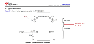
Here an SCB is applied at the voltage divider. But the voltage at Vout of Tracker may not rise to SCB voltage. This can cause a reverse current flow. 

Given that the datasheet mentions a maximum reverse current (IREV) of 0.25 µA, I would like to understand how the tracker device will respond to this condition. Specifically, will the reverse current still be limited to the maximum IREV mentioned in the datasheet, or should I expect a higher reverse current due to the condition not being met?

  • Hey,

    The internal design of the TPS7B4255-Q1 is meant to keep reverse current to its specified maximum, even if VOUT is driven externally above VIN. You generally should not see a higher reverse current than the datasheet value unless operating conditions exceed the devices recommended ratings. If you have an opportunity to measure the actual reverse current in your application, the data can help confirm that the device behaves as expected

    Hope this helps,

  • Hii, Thanks for the response,

    I tried the setup with an Ltspice simulation. Unfortunately I am getting a huge reverse current for higher voltages. The design is a proposal and I dont have an actual circuit with me. How can we resolve this ambiguity?

  • Hey mahesh,

    sorry that you're having discrepancies. Can you please confirm that you're using the TI official model?

  • Hii,

    Yes I am using the Pspice model from TI,

    TPS7B4255-Q1 PSpice Transient Model (Rev. A).

    (The simulation is done in LtSpice). 

    Thanks

  • Hey Mahesh

    Thanks for following up on this. Here are a few considerations that might help resolve the discrepancy you’re seeing with the TPS7B4255-Q1 reverse current in your LTspice simulation:

    1. Model Compatibility:
      • Although TI provides PSpice models, running them on different simulators (like LTspice) can sometimes introduce unexpected behavior. There may be aspects of the PSpice model that do not directly translate into LTspice.
      • If possible, try using the official model in the simulator environment recommended by TI (e.g., PSpice for TI, TINA-TI, or another tool TI supports). This helps ensure the model is used under conditions it was fully validated for.
    2. Simulation Setup:
      • Double-check that all pins (VIN, VOUT, GND, and any other relevant pins) are configured exactly as described in the datasheet’s recommended operating conditions.
      • Ensure that any external components (resistor dividers, input sources, loads) are the same as in your intended real-life application. Mismatch in load or supply conditions can cause unexpected behavior, especially regarding the body diode or other internal protection devices.
    3. Model Limitations vs. Datasheet:
      • The datasheet’s limit of 0.25 µA for reverse current is measured under specific test conditions that might not be identical to your simulation. In some corner scenarios or at voltages beyond recommended operating levels, you might see modeled internal parasitics that cause higher currents in simulation.
      • The device itself is designed to limit reverse current, so real hardware typically follows the datasheet values when operated within spec. A simulation result that drastically exceeds the datasheet spec under normal conditions may be due to how the simulator handles internal device structures rather than a genuine device issue.
    4. Next Steps / Verification:
      • If it is feasible, validating with a real hardware prototype (or an evaluation board) can confirm the actual reverse current behavior.
      • If the discrepancy remains a concern or if building hardware is not currently possible, consider running the same test scenario in a TI-recommended simulator to confirm whether the results align with the datasheet.

    Ultimately, the datasheet specifications and real hardware behavior should have priority over simulation anomalies, especially when the model is ported to a simulator that isn’t natively supported. Please let me know if you have additional details about your test conditions or if you try a different simulator and see the same behavior.

    Hope this helps,

    Vahnroy