This thread has been locked.

If you have a related question, please click the "Ask a related question" button in the top right corner. The newly created question will be automatically linked to this question.

LM5177: Externel Gate Driver Requirements

Part Number: LM5177
Other Parts Discussed in Thread: UCC27211

Tool/software:

Hi,
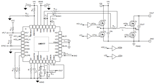
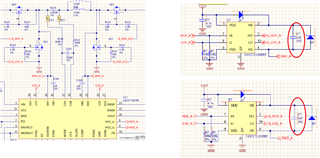
I used LM5177 and I will add external gate driver for 12V gate drive.
Board will operate both buck/buck-boost/boost modes.

IC can generate 100% duty for HO pins but half bridge drivers can't charge bootstrap capacitor when 100% duty applied.

Can I have to use 2 isolated converter for boostrap charge or is there easier solution?

At datasheet this is written:

"If the device is in boost or buck mode, the
other half bridge high-side switch needs to be permanent on. The internal gate drivers support this by sharing
the current from the other half bridge, which is switching. Therefore, a minimum of quiescent current can be
assured as no additional char pump is needed."

How can IC internally do that and Can I make same solution with UCC27211 just using 12V  supply(which is ground referance)? 

  • Hi Mustafa,

    i am not the expert for the UCC27211 but it looks like it accepts logic level input for the control signals.

    So you could use the LOx and HO_LLx signals to control the UCC27211.

    Note: you still need to maintain the Boot circuit so SWx, HBx, HOx need to be connected as shown in the datasheet.

    Best regards,

     Stefan

  • Hi Stefan,

    When there is no low side switching, External Gate drivers boostrap capacitor won't charge and gate driver cant supply 100% Duty for high side mosfet.

    At buck mode, boost circuits high side mosfet have to be fully ON. 

    At boost mode, buck circuits high side mosfet have to be fully ON. 

    has LM5177 solution with this problem when gate driver added (like low frequency low side switching to charge boostrap)?

    At datasheet that written :

    "Make sure the supply voltage V(extGD)
    for each external gate driver maintains the necessary requirements for a 4-switch Buck-Boost such as 100%
    duty cycle and the isolation between each side of the full-bridge."

    "If the device is in boost or buck mode, the
    other half bridge high-side switch needs to be permanent on. The internal gate drivers support this by sharing
    the current from the other half bridge

    How can I make The external gate drivers support 100% duty by sharing
    the current from the other half bridge?

  • HI Mustafa,

    you already found the answer in your question: "The internal gate drivers support this by sharing
    the current from the other half bridge"

    There is an internal charge sharing circuit which maintains that.

    Therefore as already mentioned above:

    "Note: you still need to maintain the Boot circuit so SWx, HBx, HOx need to be connected as shown in the datasheet."

    So connect as shown in the datasheet with the only exception that the digital gate control signal of the high side driver is connected to HOx_LL instead of HOx

    Best regards,

     Stefan

  • Hi,

    Look at the my schematic design. I know There is an internal charge sharing circuit which maintains 100% duty but normal half bridge drivers (which I will use externally )dont have that.

    I'm asking for External gatre driver. To charge Red circled capacitors SW node have to be GND for some time interval.

    At 12 to 24V conversion SW1_A node always 12V and its capacitor never charged. So external gate driver can't  keep Q10 mosfet ON,

    Similarly At 24 to 12V conversion SW2_A node always 12V and its capacitor never charged. So external gate driver can't  keep Q11 mosfet ON.

    I'm asking internal charge sharing circuit for apply that externaly to external half brick gate drivers.

    I'm open with any simple solution for make the  external gate driver to give 100% Duty for high side Mosfet.

  • Hi Mustafa,

    in this case (as the gate driver requires 12V) there is only the option to provide isolated 12 V for each phase to supply the HB from this and maintain its voltage level.

    Best regards,

     Stefan