This thread has been locked.

If you have a related question, please click the "Ask a related question" button in the top right corner. The newly created question will be automatically linked to this question.

UCD3138: No PMBus devices responded to a DEVICE_ID request

Part Number: UCD3138
Other Parts Discussed in Thread: USB-TO-GPIO2,

Tool/software:

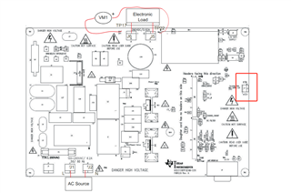
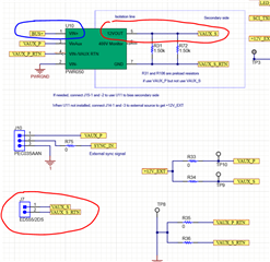
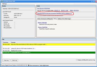
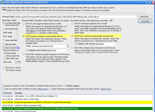
I used the ucd3138 chip to try to burn the program, when my development board was connected to 110v power supply or 12v auxiliary power supply, I could successfully burn the program, but when the two power supplies were connected at the same time, I could not burn the program. I need you guys to help me figure this out. My sincere thanks.

  • Hello,

    Can you please elaborate on your test setup? What UCD3138 board are you using and what topology? Wh0y are you connecting two different power supplies at the same time? What are the voltages of each power supply?

    We have seen issues where if you provide the main power supply (Ex. Vin = 390VDC for LLC) and provide 5V aux power via the USB-TO-GPIO2 adapter, then the UCD3138 will not perform properly. This is because of a grounding mismatch between your laptop and the main power supply. This is a common issue for any part, not just the UCD3138 (Ex. I have seen issues with op amp performance when two different power supplies are added). I would recommend using only one power supply at a time to ensure the grounding is the same.

    Regards,

    Jonathan Wong

  • First of all, thank you for your reply, I am using UCD3138PFCEVM-026 board, on the basis of this code to modify totem pole PFC. I used 110v AC for the power input and 12v for some drives. If you want to resolve whether you need to write a checksum, let the program start itself. thank you.

  • Hello,

    What terminal are you applying the 12V to? I do not understand the "12V for some drives" part. 

    Regards,

    Jonathan Wong

  • Thank you for your reply. I see that UCD3138PFCEVM-026 is also powered separately, and the board I designed is based on some of them. If 110v AC input and 12v power supply at the same time, I will not be able to burn programs using the USB-TO-GPIO2 adapter. thank you.

  • Hello,

    J7 is an OUTPUT not an input. The J7 is the output of the PWR050 auxiliary flyback bias supply. The PWR050 takes the boost converter output (BUS+) and provides an isolated 12V supply. You only need the 110VAC input and the UCD3138PFCEVM-026 will take care of the rest.

    The PWR050 Altium Files are found here: https://www.ti.com/lit/zip/slur924 

    Regards,

    Jonathan Wong

  • Okay, thank you very much.

  • Hello, when I was using the memory debugger, I was suddenly powered on, and something was wrong with it. Then the chip into rom mode, and can not burn the program,may I ask this is the chip itself reset?

    Error reading from the device: error reading memory or EEPROM at address 0x191EC; PARM_INFO write Base: 0 (RAM), Offset: 0x01EC, Count: 4, Size: 1 [0x00EC010401] on PFC SinglePhase Shunt @ Address 88d error: NACK Please check your device connection.

  • Hello,

    Try turning off and on the input power supply. If you are operating the UCD3138PFCEVM-026, then I recommend supplying 3.3V power via the UCD3138PFCEVM-026 instead of the USB-TO-GPIO2. If you use the Fusion Studio Online GUI, then the code will automatically execute in program mode. Or, you can manually command the UCD to execute its program using the UCD3xxx Device GUI with the 0xF0 pmbus command.

    Regards,

    Jonathan Wong

  • Thank you very much, I will try to use the onboard 3.3v power supply for the program to start itself, and not use the USB-TO-GPIO2 to provide 3.3v. By the way, without boot, how many bytes of checksum have to be written, and know what the checksum is?

  • Hello,

    I will provide a response tomorrow.

    Regards,

    Jonathan Wong

  • Hello,

    What do you mean by "without boot, how many bytes of checksum have to be written"? You cannot overwrite the Boot ROM since it is the read-only firmware that is etched into the UCD3138 when manufactured.

    Regards,

    Jonathan Wong

  • Hello,

    I wrote the checksum as shown below, and the program was able to start itself, but I couldn't get back to rom mode using the 0xD9 instruction. Can I go back into rom mode through the back door. Here is the backdoor code in the program.

    Regards,

    Yuxin Liu

    if((MiscAnalogRegs.GLBIOREAD.bit.FAULT0_IO_READ == 0) || (PMBusRegs.PMBCTRL1.bit.SLAVE_ADDR == 0x7e))
    	{
    		pmbus_read_write_rom_mode(PMBUS_WRITE);
    	}

  • Hello Yuxin,

    Yes, you can go back to ROM mode using this hardware backdoor code IF it is located in the beginning of your code. Here are the steps to jump back to ROM mode:

    1. Manually pull FAULT0 pin to GND
    2. Reset the power to the UCD3138. You can use the RESET button if you are using a UCD3138 EVM
    3. Scan for the UCD3138 devices again via ROM mode using the UCD31xx Device GUI.

    Regards,

    Jonathan Wong

  • Thank you for your help.