This thread has been locked.

If you have a related question, please click the "Ask a related question" button in the top right corner. The newly created question will be automatically linked to this question.

BQ25798: Premature charge termination prevents gas gauge from waking up

Part Number: BQ25798
Other Parts Discussed in Thread: BQ40Z50,

Tool/software:

Hi there—our design comprises the BQ25798 with a 1S4P battery pack that uses the BQ40Z50 for primary protection. The programmable shutdown threshold of the BQ40Z50 is set to 2.6 V in our application, and the BQ40Z50 has a non-programmable shutdown threshold of approximately 2.2 V.

I have replaced the cells in the battery pack with a Keithley 2308 cell simulator to test the interaction between the BQ25798 and our battery pack's protection board during various conditions. The regulated output of the Keithley 2308 is referred to as VCELL in the notes below.

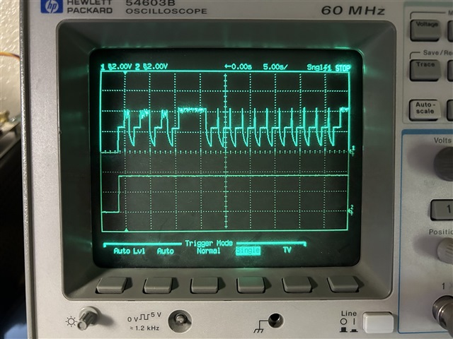
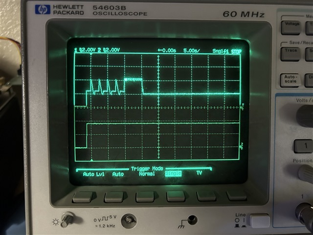
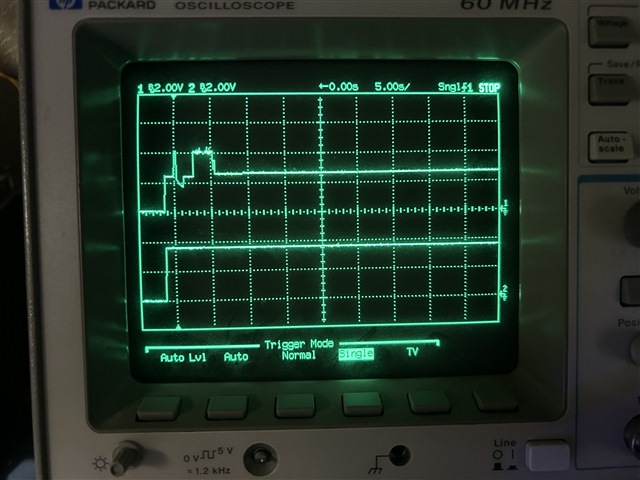
I find that if VBUS is applied while VCELL = 2.5 V (less than the programmable shutdown threshold of the gas gauge), the BQ25798 rapidly enables and disables VBAT as in channel 1 (top) of the capture below. VSYS is stable as in channel 2 (bottom) of the same capture.

The cell simulator shows no current actually flows into the cell; therefore, the battery pack does not charge during this condition. Since VBAT (i.e. the pack voltage from the perspective of the gas gauge) is repeatedly applied and removed, the gas gauge never wakes up.

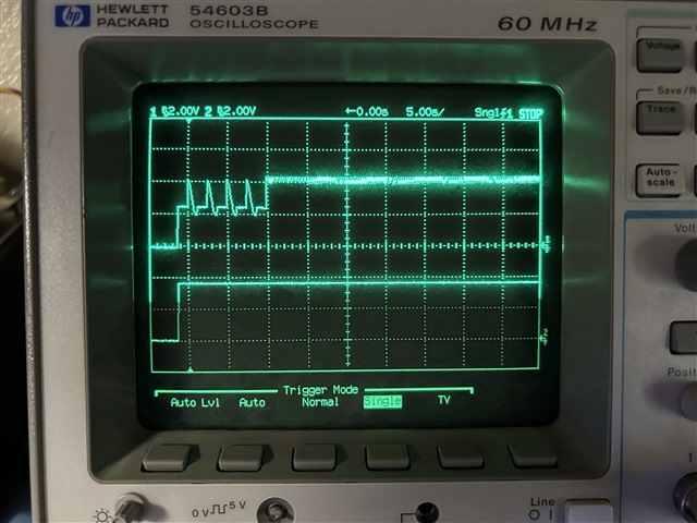
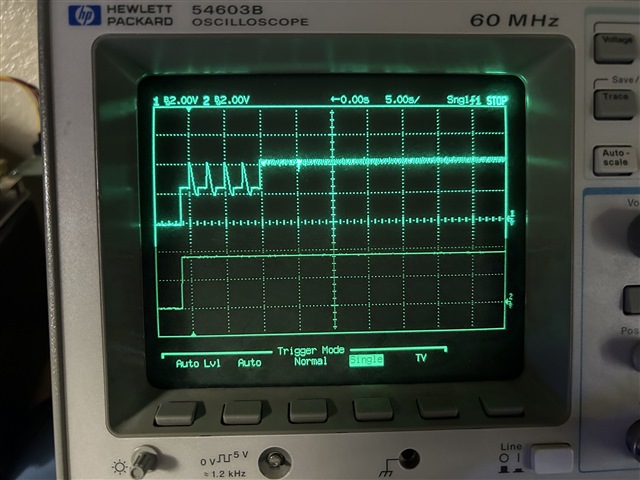
Conversely if VBUS is applied while VCELL = 2.7 V (greater than the programmable shutdown threshold of the gas gauge), the condition settles very quickly; VBAT remains enabled and is pulled down to VCELL, and the cell simulator shows that the desired precharge current flows into the cell:

Based on the registers read from BQ25798, it seems it is repeatedly cycling among trickle charge, termination complete, and taper charge:

     0  1  2  3  4  5  6  7  8  9  a  b  c  d  e  f
00: 02 01 b8 01 f4 24 00 64 8c 0f 03 00 dc 4b 3d a2
10: 80 00 10 01 14 aa c0 7a 55 00 64 0f 2a 00 10 10
20: 00 00 00 82 10 10 20 00 ff c7 7f 1f ff fc 80 00
30: 00 01 6a 00 00 13 1c 12 ff 12 fe 09 a0 0b 5f 02
40: 67 00 25 00 1b 00 1b 00 19 ff ff ff ff ff ff ff

Another instance:

     0  1  2  3  4  5  6  7  8  9  a  b  c  d  e  f
00: 02 01 b8 01 f4 24 00 64 8c 0f 03 00 dc 4b 3d a2
10: 80 00 10 01 14 aa c0 7a 55 00 64 0f ea 01 00 00
20: 00 00 00 82 10 00 20 00 ff c7 7f 1f ff fc 80 00
30: 00 01 24 00 00 14 23 13 1e 13 1c 09 a4 0b 62 02
40: 67 00 25 00 1a 00 00 00 19 ff ff ff ff ff ff ff

Another instance:

     0  1  2  3  4  5  6  7  8  9  a  b  c  d  e  f
00: 02 01 b8 01 f4 24 00 64 8c 0f 03 00 dc 4b 3d a2
10: 80 00 10 01 14 aa c0 7a 55 00 64 0f 8a 01 00 00
20: 00 00 00 82 10 00 20 00 ff c7 7f 1f ff fc 80 00
30: 00 01 10 00 00 13 19 14 11 13 18 10 89 0b 65 02
40: 67 00 25 00 1b 00 1c 00 19 ff ff ff ff ff ff ff

Also of note is that while the BQ25798 operates in trickle charge, VBAT_PRESENT = 0 and VSYS_STAT = 1 (VSYSMIN regulation). During charge termination and taper charge, VBAT_PRESENT = 1 and VSYS_STAT = 0; this is confusing, as VSYS is clearly in VSYSMIN regulation throughout the entire sequence of events.

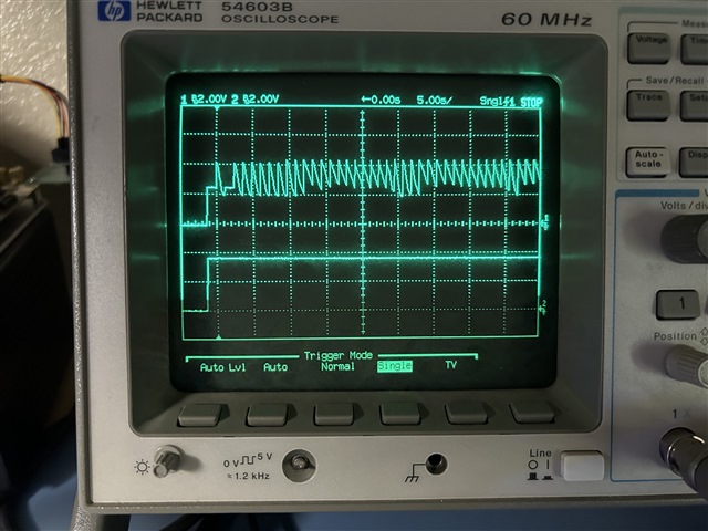
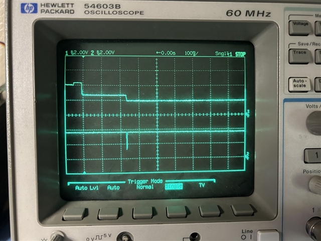
On a hunch, I lowered TRECHG from the default (1024 ms) to the minimum (64 ms) so that VBAT cannot collapse significantly. Now, VBAT remains enabled even for VCELL = 2.3 V (greater than the non-programmable shutdown threshold of the gas gauge):

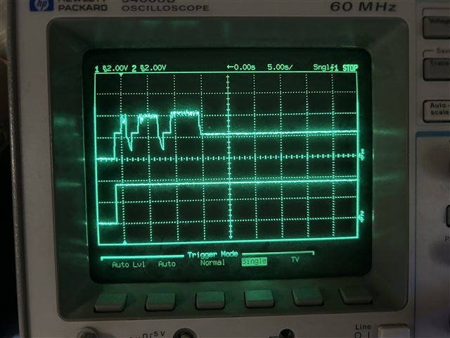
The couple of brief oscillations occur because our system firmware cannot lower TRECHG until a few seconds after the system boots, and TRECHG remains the default (1024 ms) for a brief time. The 5-second period that follows appears to correspond to the non-recoverable undervoltage protection delay in our gas gauge, during which it waits to enable the CHG FET.

What I suspect to be happening here is that after the gas gauge wakes up, it disables zero-volt charging and opens its CHG FET for 5 seconds; charging current falls below the termination current, and the BQ25798 immediately jumps to the termination state from any other charging state.

We have seen similar behavior when the CHG FET opens due to some other reason triggered by the gas gauge (e.g. overtemperature)—the BQ25798 briefly believes charging is complete, before it attempts to restart charging, and VBAT OVP is triggered as a result of the CHG FET remaining open. Please consider the following questions:

[1] Are these results expected—including the "jump" from a relatively early charging state (e.g. trickle) to termination, as well as the various values returned for VBAT_PRESENT and VSYS_STAT?

[2] Is there any risk in lowering TRECHG as I have done, or would any other workaround be more preferable?

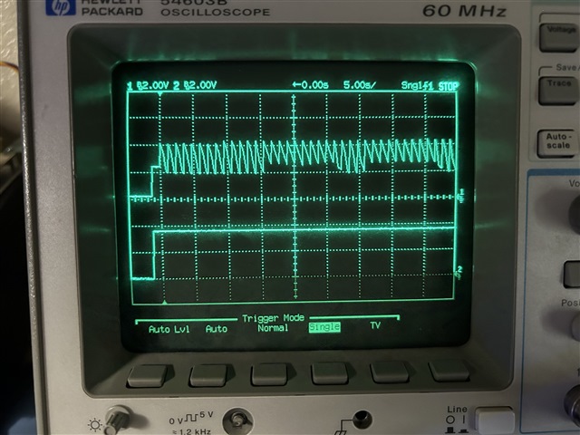
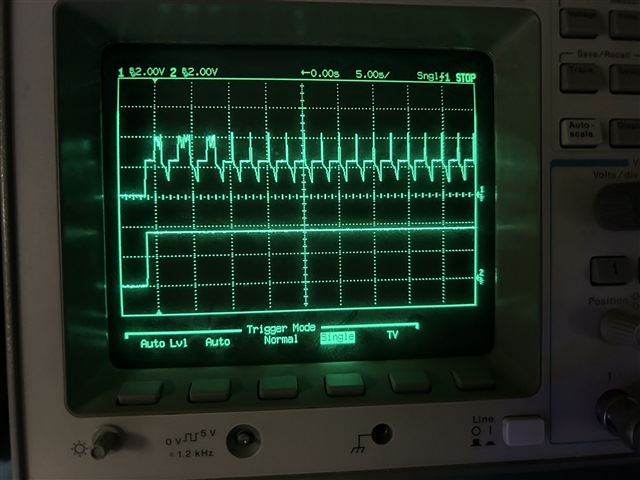
With this workaround in place, I noted another behavior for VCELL = 2.1 V (less than the non-programmable shutdown threshold of the gas gauge):

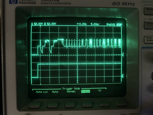
Here, it seems that VBAT remains enabled, but consistently cycles among VREG, VCELL and 2.5 V (the trickle charge regulation voltage). Once more, the cell simulator shows no current actually flows into the cell. I suspect that in this case, the zero-volt charging current of the gas gauge is less than the termination current, and the BQ25798 repeatedly stops and re-starts charging for the same reason.

[3] Is this last result expected? We ultimately wish to implement secondary non-recoverable undervoltage protection in the range of 2.0–2.2 V; therefore, it's actually preferred that the battery cannot be recharged below VCELL = 2.3 V anyway. However, I'd like to understand the mechanism here, and whether or not it can be predictable across operating conditions.

Thank you in advance for your support—in case I can clarify any of my observations or questions, please let me know.

  • Hi Jeff,

    SYSMINSTAT=1 whenever V(SYS) > V(BAT) and the minimum system regulation loop is active.  VBAT_PRESENT=1 does not come on until the charger is out of trickle charge. There are deglitch times for the all of events you are seeing that delay VBAT_PRESET being set so I don't recommend relying on that bit.

    The results above are expected, unfortunately.  With no battery or protector FET open, the charger starts in trickle, then pre then fast then OVP then charge stops and repeat. The timing of the pulsing is a function of the capacitance on BAT, recharge threshold, recharge timing and auto discharge at OVP registers.  There is current flowing in short pulses so eventually the pack would charge. 

    The simplest but costliest fix to prevent the OVP and pulsing is to add 200uF (slightly less if charge current is set low) to BAT pin.  The other "workarounds" (like changing VRCH timing or threshold) do not prevent the pulsing but change the frequency.  I am surprised that you found a setting that quickly prevents the pulsing.    

    Regards,

    Jeff

  • Hi Jeff—thank you for your prompt reply. We currently have about ~30 uF on VBAT; perhaps that's why we were able to work around this problem by lowering TRECHG alone.

    Our next revision happens to be in layout, but the height is very constrained in this area; I will see whether we can manage one 6.3-V 220-uF tantalum here. A couple questions about that solution:

    [4] Is the idea that VBAT would be driven to OVP one time, then the bulk cap would sustain VBAT until the protector FET closes after the gas gauge's 5-second startup time?

    I presume the VCC pin of the gas gauge is drawing its own active-mode current through the body diode of the protector FET during this 5-second delay; that's an awfully long time, even for 200 uF.

    [5] Where does 200 uF come from—is it based on any system-level factors, and is there any upper limit?

    In the meantime—for the last case with TRECHG = 64 ms and VCELL = 2.1 V, the gas gauge is shut down entirely; the protector FET is not open per se, but presumably operates in the ohmic region on behalf of the zero-volt charging function of the gas gauge.

    It looks like VBAT holds steady at 2.5 V for 1–2 seconds, then hits OVP; I presume this corresponds to the point at which the charger moved from constant-voltage trickle charge to constant-current precharge, at which point the ohmic protector FET looks like an open circuit.

    [6] Is this 1–2 second delay the internal deglitch time you mention?

    Last but not least—it seems the 5-second startup time of the gas gauge (i.e. the "SUV delay") is at least partially responsible for this issue. From the gas gauge's technical reference manual:

    I will test with this start-up time disabled; in case you have any additional thoughts, please let me know. Thanks again for your continued support!

  • Hi Jeff,

    Regarding 4, the big cap prevents OVP.  So charge repeatedly terminates and recharges, creating a much smaller oscillation on BAT pin.

    Regarding 5, the 200uF is based on my empirical testing.  I don't have a closed form equation.  Some settings, like IINDPM or ICHG<0.5A or certain VBUS to VBAT combinations, allow for slightly lower capacitance (like 100uF).  200uF seem to address all VBUS to VBAT configurations at the default ICHG=1A.

    If VBAT < 2.5V, the charger regulations BAT to 2.5V with only 100mA trickle current for 1.5s before transitioning to precharge then fast charge.

    Regarding 6, per design, there are several deglitchs, some of which are not even in the internal spec, that affect the OVP enter/exit, recharge enter/exit, termination enter, etc.  

    I recommend also enabling/disabling the auto 30mA pulldown at BAT OVP if you haven't already.

    Regards,

    Jeff

  • Hi Jeff—thank you for your comprehensive feedback; I apologize for my delayed response. I am happy to report that this problem is solved by adding a large bulk capacitance to VBAT according to your suggestion, and adjusting the registers described in this thread.

    First, I returned TRECHG to its default value (1024 ms) and confirmed that the original problem can be reproduced with VCELL = 2.1 V and no additional bulk capacitance on VBAT. In all of the captures that follow, VBAT and VSYS are shown on channels 1 (top) and 2 (bottom), respectively.

    Next, I added 220 uF to VBAT and confirmed that the oscillation is much less pronounced, presumably because the charger reaches termination before OVP and hence restarts much more quickly.

    The maximum period of the sawtooth is equal to the 1.5-second delay to precharge, plus TRECHG. Often, the period is smaller as the charger appears to go straight to precharge as soon as the gas gauge briefly wakes up.

    I polled register 0x20 (fault flag 0) as fast as my system would allow, and confirmed that VBAT OVP is never triggered throughout the sawtooth. This change alone is not enough to consistently keep the gas gauge awake, but the OVP problem is solved.

    Next, I set EN_AUTO_IBATDIS = 0 to disable the 30-mA pulldown. I did not see any difference in the VBAT waveform—however, this seems expected since VBAT OVP is no longer triggered anyway.

    Next, I reduced TRECHG to its minimum value (64 ms) again. Our system firmware takes several seconds to start, so the sawtooth is not immediately relieved. Once the register is written, however, we see VBAT hold much more steady as charging repeatedly restarts almost instantly.

    Notice there is still a problem here, as VBAT stays near VREG and is not loaded down by VCELL, indicating the protector FET is still open. The current readout of the cell simulator confirms the pack is not charging.

    Reading the gas gauge registers confirms it is not in any fault state; rather, it operates in zero-volt charging mode for VCELL < 2.2 V. In this case, the protector FET operates in the ohmic region, and is not fully enabled; this is expected behavior for BQ40Z50.

    I lowered the zero-volt charging threshold of the gas gauge to 1.8 V. Now, we can see the protector FET is open for only 5 seconds; this corresponds to the blanking period during which the gas gauge waits to enable the protector FET.

    Afterward, the protector FET closes and VBAT is pulled down to VCELL. Finally, the current readout of the cell simulator confirms the pack is charging steadily.

    Last but not least, I repeated this experiment with VCELL = 1.9 V. In this case, the protector FET stays open after the 5-second blanking period. This is by design, and corresponds to the non-recoverable undervoltage protection we've enabled in the gas gauge for VCELL < 2.0 V.

    We've added a 220-uF bulk capacitor to VBAT in our next PCB revision. In the meantime, I just wanted to confirm the following with you:

    [7] Is there any drawback to lowering TRECHG to the minimum value (64 ms), such that charging restarts almost instantly?

    [8] With the charger no longer cycling in and out of OVP, do you still recommend disabling the 30-mA pulldown? This change no longer seems necessary, and the pulldown would be useful in case of a legitimate OVP fault.

    Thanks again for your continued support—in case I can clarify any of my questions or observations, please let me know.

  • Hi Jeff,

    Great news and documentation!  I will use this thread for other customers having issues with BQ40Z.

    Regarding 7, the TRECHG is a time hysteresis.  If the battery's impedance is high, it's cell will relax after termination, resulting in the charger going in and out of recharge more quickly.  Otherwise, I don't see an issue.  You can work around that using the top off timer, i.e. delay termination to give time for the battery to relax.

    Regarding  8, there is no need to disable the pull down since undesired OVP no longer occurs.

    Regards,

    Jeff

  • Hi Jeff—thank you for your kind words! I'm glad to hear this investigation can benefit others. I'm aligned with you on questions [7] and [8]—just one last question for now:

    [9] For these extreme cases where the BQ40Z50 can't complete its 5-second start-up sequence until after our system firmware intervenes and lowers TRECHG, I see a brief glitch on VSYS (channel 2) at the instant the BQ40Z50 closes the protector FET and VBAT is pulled down to VCELL:

    I only spotted this because I found our system was rebooting at this same moment. I also found that if VCELL is low enough such that the BQ25798 starts in trickle charge, the "battery" briefly takes at least 500 mA before settling to the 100-mA trickle charge current:

    Do you have any thoughts as to why either of these phenomena occur? This is all very harmless, as the system still recovers; we're also talking about an extremely unlikely scenario in the first place. I'm mostly asking out of curiousity.

    Thanks again for your continued support—in case I can clarify any of my observations, please let me know.

  • Hi Jeff,

    The glitch on SYS is expected.  It is a like a load transient. More cap on SYS might help reduce.

    The 500ms settling time for trickle charge is odd.  Below is a plot of start up profile for a 1S app (yellow is BAT).   There is no battery attached, only a 0.1F capacitor on BAT.  The charger starts trickle, then there is a deglitch period from trickle to precharge where current reduces then precharge then fast charge.  Are you seeing the deglitch?

    regards,

    Jeff

  • Hi Jeff—thanks again for your feedback, and for sharing this capture.

    We have at least 500 uF on VSYS, and can't easily make room for much more. However, the early reboot caused by this glitch isn't necessarily visible to the customer—it also only seems to occur for extreme values of VCELL that we don't reasonably expect to see, so I think we can live with it.

    Another option we can explore is to delay some of the boot sequence in our system firmware, and reduce the demand on VSYS until the gas gauge is stable. I think my main point of confusion here is why we see a glitch on VSYS, but not VBAT—aren't they fundamentally sourced from the same switching converter?

    Regarding the trickle charge deglitch time—I typically see VBAT hold steady at 2.5 V for roughly 1.5 seconds before precharging begins; based on your comment earlier, I believe this is expected.

    However, what I'm referring to here is the brief 500-mA charging current shown by the cell simulator meter in the video, coincident with the protector FET closing and trickle charge starting. In this experiment, VCELL is held just low enough (2.05 V) to prevent precharging.

    I have been loosely assuming this is also a load transient, as the BQ25798 naturally takes a small amount of time to limit the charging current to 100 mA as soon as a load is introduced. In case I have misunderstood or I can provide any additional data, please let me know.

  • Hi Jeff,

    Sorry, I misunderstood.  I thought that was a glitch on BAT.  IF VBAT>MINSYS, I would not expect a glitch since BATFET is fully on, tying BAT to SYS pin, especially with your SYS capacitance.  If 2.5V<VBAT<MINSYS, the BATFET current is being linearly regulated and the response time is controlled by that linear regulation which is slow.  If VBAT<2.5V, the 100mA trickle charge is a fixed current source so i=C*dv/dt.

    I can't explain the 500mA charge current.  Until BATP=VREG, the BAT pin output is essentially a current source providing ITRICK, IPRE, IFAST based on VBATP voltage.  The transitions are somewhat "digital" but the analog FB loops (except for trickle charge) take a few ms to respond to the transient.

    Regards,

    Jeff  

  • Hi Jeff—thank you for these additional details; I am aligned with you on all of this. I will reach out in case I have any additional questions—thanks again!