Tool/software:
Hi team,
My customer asked if you can provide some suggestions on TPS6593-Q1 all power rail OVP and UVP bench test setup? Thanks
Best Regards,
Xiawei Zhang
This thread has been locked.
If you have a related question, please click the "Ask a related question" button in the top right corner. The newly created question will be automatically linked to this question.
Tool/software:
Hi team,
My customer asked if you can provide some suggestions on TPS6593-Q1 all power rail OVP and UVP bench test setup? Thanks
Best Regards,
Xiawei Zhang
Hi Kaite,
Yes, customer want to perform their own testing of OVP/UVP to see if the protection will work as expectation.
Best Regards,
Xiawei Zhang
Hi Xiawei,
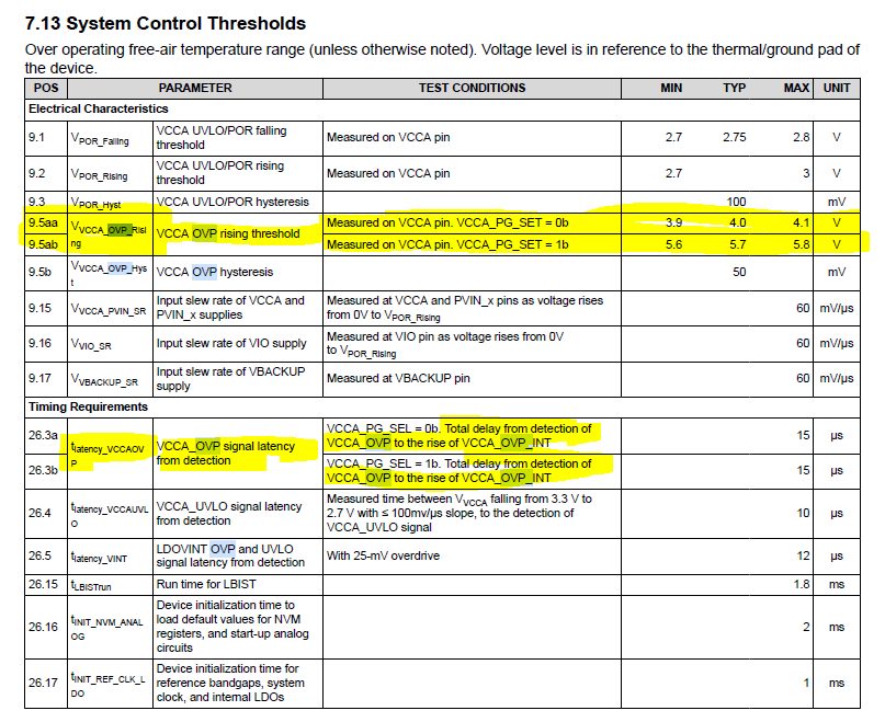
This is a more system-level question depending on their situation. If they are trying to cover what situations in their system could trigger OV/UV they will need to do an analysis on this and then try to force those condition to then trigger/test the part. Otherwise if they are just considering the TPS6593-Q1 device in isolation, I'm unsure why they are needing to test as this is already validated by TI per datasheet. In general, for OV, you can induce the condition artificially by raising the voltage input in question, e.g. VCCA, above the OPV threshold listed in the datasheet - the datasheet also lists the test condition mentioned for these specs. As one esample, section 7.13 of TPS6593-Q1 datasheet System Control Thresholds lists the VVCCA_OVP_Rising threshold and test condition, as well as hysteresis, and then the latency for the detection to the VCCA_OVP_INT rise.

This should allow you to define a test condition.
Regards,
Katie
Hi Kaite,
Could you please provide some hardware setup example about how to trigger the UV and OV? Can they connect the output to power source directly?
Best Regards,
Xiawei Zhang
Hello Xiaowei,
For the OV, they can connect a diode in series to a power supply (PS) connecting to the ANODE, this will be the OV supply and have the cathode connect to the power output to test.
The PS can be set higher than the drop across the diode plus the setting for the BUCK/LDO output so that it higher than the PGOOD setting for the power output, then the interrupt/fault reaction occur after assert of the PS.
For the UV, hardware wise that is rather difficult.
One suggestion would be that the customer write to I2C to disable the power rail, doing so will keep the VMON active and monitoring the output which will be dropping because of the disabling of the power rail. The device will see the UV and the interrupt/fault handling will occur as well.
A suggest hardware wise for testing the BUCK for the UV events would have a test point access to the FB_Bn pins then auxiliary hardware can be at least used if a test strategy is found.
BR,
Nicholas McNamara