


Part Number: TPS2117
Tool/software:
Hello, we have encountered the following problems when using your TPS2117DRLR:
Our TPS2117 is used for a mobile smart device; This device has 2 batteries, the main battery is connected to the VIN1 end, the backup battery is connected to the VIN2 end;
The purpose is that when the customer unplugs the main battery, the backup battery can be perfectly connected to the power supply. Prevent power failure of the device.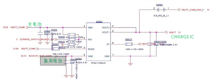
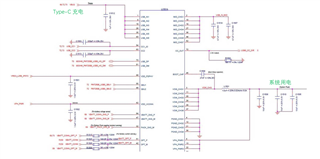
At the same time, the VOUT of our TPS2117 is connected to a charge IC of Qualcomm: PM-7250B-2-FOWPSP110-HR-00-0.
The charge IC also accepts type-C power supply; Charge the battery; And the function of the battery to power the system.

Now the questions are as follows:
1. Based on the current test results, the TPS2117 can only support approximately 1.4A of battery charging current when operating from VOUT to VIN1. This supply current is lower than our target design requirement of 3A for battery charging. Is there a feasible method to enhance this performance? Additionally, what are the associated costs and potential trade-offs, such as temperature rise, stability issues, or an increase in internal resistance over prolonged use?
Upon reviewing the specifications, the upper limit of reverse power supply current for this device is stated as 4A. However, the current model only achieves 1.4A. Is it necessary to adjust specific pins or parameters to achieve higher performance? Alternatively, should we consider changing to a different chip to meet the design requirements?

2 When the adapter is inserted or the handshake protocol is completed, the VOUT voltage will suddenly increase to 4.8V, and then our system LOG will warn us that there is an overvoltage problem and stop the battery power supply
(Overvoltage is when the battery voltage is higher than our preset threshold voltage, stop the battery power supply)
Then, when the voltage is reduced, the power supply continues. What is the cause of this problem? We tried to blow tps2117 down and weld VIN1 and VOUT directly without this problem. Is there a solution?

3. Our battery has overdischarge, and VIN1 voltage is 0V after the battery overdischarge. In theory, the backup battery will be directly switched over to supply power. May I ask if VIN2 is also 0V, TPS2117 cuts back to VIN1?
4. Will the charge IC directly supply power to VIN2 if I remove the main battery when the battery is charging?
