This thread has been locked.

If you have a related question, please click the "Ask a related question" button in the top right corner. The newly created question will be automatically linked to this question.

BQ25750: Temp. of ACFETs and BATFETs are very hot.

Part Number: BQ25750

Tool/software:

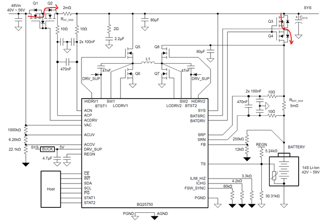
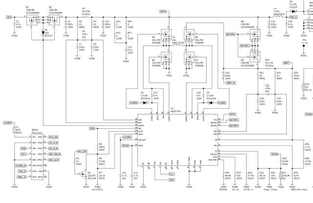
I designed a 50V/10A charger with BQ25750 and charged well.

But one of Back-to-Back ACFET (BATFET) was heated up to 120 Celcius.

I think that the current flow through parastic diodes of Q2 and Q4.

I wonder if this condition is normal.

I'll be waiting for kind answer.

Thank you~!

  • Hello Jang-sik,

    Thanks for working on this. This condition is not normal. I have a few questions to help debug this:

    • Can you send me your schematics?
    • Can you send me the datasheets for the ACFETs and BATFETs?
    • Can you measure the voltage on ACDRV compared to VAC and BATDRV compared to BATSRC while those FETs are ON?

    Best Regards,
    Ethan Galloway

  • Hi Ethan,

    Thank you for kind reply.

    1. ‎My first schematic of BQ25750 is as below.

     - Input : V50 (50V)
     - Output : VSYS (50V/8A)
                     VBAT (1A charging up to 50V)
       During the prototype test, VSYS was measured 49.3V and Q2 was heated over 100 Celcius.
       So I thougth that all current flowed via parasitic diode of Q2.

    2. ‎4 FETs are all ISC025N08NM5LF2 (Infineon) .

    3. I didn't have enough time to debug so I changed 2-`Back-to-Back FET block` to 2-`Ideal diode block` as below.


        After change, I could not find any voltage drop and heated FET.
        I don't have PBA from first schematic so I can't measure any point of your suggestion now.

    I have to revise this charger and I want to use the functions of BQ25750.
    Ideal Diode is not good solution for this charger.

    Best Regards,

    J Won.

  • Hello J Won,

    Thanks for the new information. I have a few more questions to help debug this:

    • Can you measure the voltage on the gate of Q2 compared to ACDRV when ACDRV is ON? Can you also measure ACDRV compared to VAC?
    • Can you measured ACDRV and BATDRV with an oscilloscope?

    For the schematic, I have few recommendations:

    • I recommend installing a DNP low pass RC filter from BATDRV to BATSRC.  This will help if you need to calibrate the turn-ON and turn-OFF time.
    • I also recommend installing a DNP capacitor from the gate of Q8 to the drain of Q8. This will also help calibrate the FET turn-ON speed.
    • The BTST capacitors of C17 and C22 need to be 100nF.
    • Because VBAT is larger than 30V, you may need to use auto reverse mode or use an external power path solution. The inrush current from these large battery voltages can be incredibly large.

    I recommend reading the FAQ on the BQ25750 power path transfer because the max VBAT is 49.4V. The inrush current from a 50V source can be incredibly large.

    Best Regards,
    Ethan Galloway