This thread has been locked.

If you have a related question, please click the "Ask a related question" button in the top right corner. The newly created question will be automatically linked to this question.

TPS23882: I am experiencing power supply issues with my PoE device when using the TPS23882

Part Number: TPS23882

Tool/software:

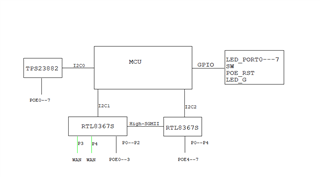
"Application: PoE power supply using the TPS23882.

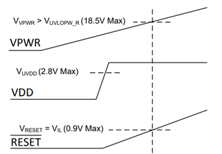
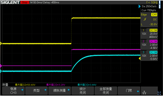
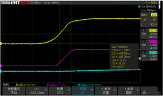
Problem: A number of TPS23882-based PCBAs fail to provide power to the connected PoE device upon initial power-up. A power cycle of the PCBA is required to establish normal operation.

Reproduction Steps: After powering down a failing PCBA, waiting for the 48V power supply to completely discharge, and then re-applying power will reliably reproduce the fault.

Analysis: Swapping the TPS23882 ICs between working and failing boards causes the fault to migrate with the IC. Root cause of the failure is unknown and the possibility of an IC defect cannot be ruled out."

  • Hi Zhan,

    Can you provide some more insight into your setup and specific test cases that are causing consistent failures? What are the register configuration settings that the device is operating in? Is the device being configured through I2C? Do you have a block diagram of the design?

    Regards,

    Brandon

  • Configuration Details:
    External configuration is handled by an MCU connected via I2C. The I2C and reset signal lines have default 4.7kΩ pull-up resistors connected to 3.3V.

    Specific Test Cases:

    1. Test Case 1: After powering down the device and waiting for it to completely discharge, when the device is powered back on, the PoE port experiences abnormal behavior when supplying power to the peripheral device (fails to power correctly).

    2. Test Case 2: After powering down the device, if a residual voltage between 8V and 10V is detected remaining on the 48V circuit, upon powering the device back on, the PoE port supplies power to the peripheral device normally.

    3. Test Case 3 / Observation: When the MCU is removed from the PCBA, testing the TPS23882 in isolation (standalone) reproduces the same issues described in Test Cases 1 and 2. Since no registers are being configured in this scenario, yet the same power supply abnormality occurs, does this phenomenon prove that the issue is unrelated to register configuration?

    4. block diagram of the design

  • Hi Zhan,

    TPS23882 requires configuration for proper operation and does not have autonomous mode feature. This feature is only in TPS23382B package, therefore for test case 3, removing the MCU I would expect to see improper behavior after a system reboot considering the configuration is lost and there is not configuration upon bootup.

    I have two guesses as to what is happening without having full details:

    1. There is a power sequencing issue occuring with your Vdd, Vpwr, and Reset pins which is keeping the device in a lockout state during these test conditions. I would recommend keeping Vdd low until Vpwr clears the UVLO condition prior. You can also keep reset pin low until Vpwr clear UVLO to ensure the UVLO latch is properly cleared. 

    I also want to note, TPS23882 is a Type-3, 30W device which per IEEE802.3bt specification requires 50V for compliant systems. This is not the issue of your system but a side note just for awareness.

    2. Your configuration and register settings can provide insight to the issue occuring why the system is not powering up. Please provide either a register dump of all register settings when this issue occurs, OR provide your configuration steps to setting the device into normal operation.

    Regards,

    Brandon

    1. The image shows the waveforms for VPWR (yellow), VDD (red), and RESET (green). Does this power-up sequence conform to the requirements?

    2. In your previous response, you mentioned multiple times that the TPS23882 does not have an autonomous mode feature and requires configuration to operate. Based on this, can we conclude the following: For the TPS23882 to operate normally, must it rely on configuration from an externally added microcontroller (MCU)?

    3. One more question: In my setup where there is no MCU present, I only added a 62kΩ pull-down resistor to pin 52. Without relying on any MCU configuration, the TPS23882 is still able to supply power normally to external devices. Is this mode of operation correct/valid?

  • Hi Zhan,

    1. The power on sequence is correct. Thank you for the waveforms.

    2. Your understanding is correct, an MCU is required to load SRAM and configure the device to operate under normal conditions. MCU structure should be similar to the following:

    3. Are you using TPS23882RTQR OR TPS23882B1RTQR. The B1 version has this feature supported, the non-B1 version does not support this mode of operation.

    Regards,

    Brandon

  • Hi Brandon,

    They use TPS23882RTQR.

    BR

    Cayden

  • Hi Cayden,

    Since they use TPS23882RTQR, they will need to interface through I2C to load correct SRAM and configure the device according to the EVM User's Guide and Data Sheet. They can also switch to the TPS23882B1RTQR which is P2P compatible and has autonomous mode feature to evaluate.

    Let me know which step is preferred and I can guide on next steps.

    Regards,

    Brandon