This thread has been locked.

If you have a related question, please click the "Ask a related question" button in the top right corner. The newly created question will be automatically linked to this question.

UCD3138: a question about CCB

Part Number: UCD3138

Tool/software:

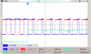
ch1:DPWM0A ch2:DPWM0B ch3:AD03

The opology is BUCK. So the dutu maybe above 50%.The DPWM mode is Multi Mode. The requirement is CBC on DPWM0A only and DPW0B duty cycle matches to DPWM0A. The DPWM Setting is as follow:

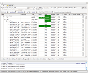
In the datasheet(Page49 table2-5), the mentioned registers have been set. But in the test wave, DPW0B is not match DPWM0A. 

FaultMuxRegs.ACOMPCTRL0.bit.ACOMP_B_THRESH = 100;
FaultMuxRegs.ACOMPCTRL0.bit.ACOMP_B_SEL = 0; /* Use threshold register for trip */
FaultMuxRegs.ACOMPCTRL0.bit.ACOMP_B_POL = 1; /* Above thresh to trip */
FaultMuxRegs.DPWM0CLIM.bit.ACOMP_B_EN = 1;
FaultMuxRegs.DPWM1CLIM.bit.ACOMP_B_EN = 1;

Can you help me to see that which register not set? Thank you very much!

  • Hello Liwei,

    Can you show your DPWM0 initialization? It looks like even before the ACOMP_B is tripped, there is already overlap between the DPWM0A and DPWM0B phases. Is there still overlap even if the CBC is disabled? There should not be any time when the DPWM0A and DPWM0B are on at the same time or else you risk overshoot. 

    Also, if the DPWM0B duty cycle matches the DPWM0A duty cycle, then if the CBC cuts DPWM0A from ex. 40% to 20%, then the DPWM0B duty cycle will stay at 40% since the CBC for phase B was not enabled. Is this the desired behavior you are looking for?

    Regards,

    Jonathan Wong

  • Hi,Jonathan Wong:

         The DPWM0A initialization is as follow:

    Dpwm0Regs.DPWMEV1.all = 20;
    Dpwm0Regs.DPWMEV3.all = (pmbus_dcdc_config[0].period >> 1);
    Dpwm0Regs.DPWMCTRL1.bit.EVENT_UP_SEL = 1;
    Dpwm0Regs.DPWMCTRL0.bit.PWM_MODE = 2;
    Dpwm0Regs.DPWMCTRL0.bit.PWM_EN = 1;
    Dpwm0Regs.DPWMCTRL1.bit.SYNC_FET_EN =0;
    Dpwm0Regs.DPWMCTRL1.bit.GLOBAL_PERIOD_EN = 1;
    Dpwm0Regs.DPWMCTRL1.bit.CHECK_OVERRIDE = 1;
    Dpwm0Regs.DPWMCTRL1.bit.ALL_PHASE_CLK_ENA = 1;
    Dpwm0Regs.DPWMCTRL1.bit.GPIO_A_EN = 0;
    Dpwm0Regs.DPWMCTRL1.bit.GPIO_B_EN = 0;
    Dpwm0Regs.DPWMCTRL2.bit.SAMPLE_TRIG_1_EN = 1;
    Dpwm0Regs.DPWMCTRL2.bit.SAMPLE_TRIG1_OVERSAMPLE = 3;
    Dpwm0Regs.DPWMCTRL2.bit.SAMPLE_TRIG1_MODE = 0;
    Dpwm0Regs.DPWMSAMPTRIG1.all = (pmbus_dcdc_config[0].period);
    Dpwm0Regs.DPWMCTRL0.bit.MSYNC_SLAVE_EN = 0; /* DPWm0 is master */
    Dpwm0Regs.DPWMCTRL0.bit.BLANK_A_EN = 1;
    Dpwm0Regs.DPWMBLKABEG.all = 20;
    Dpwm0Regs.DPWMBLKAEND.all = (pmbus_dcdc_config[0].period>>1);
    Dpwm0Regs.DPWMCTRL0.bit.BLANK_B_EN = 1;
    Dpwm0Regs.DPWMBLKBBEG.all = (pmbus_dcdc_config[0].period >> 1);
    Dpwm0Regs.DPWMBLKBEND.all = (pmbus_dcdc_config[0].period>>2); 

    The DPWM0A and DPWM0B max duty maybe 96%,so there is overlap between the DPWM0A and DPWM0B phases. The dpwm mode is multi mode. If the CBC cuts DPWM0A from ex.80% to 50%,the DPWM0B duty cycle will match 50%. Is that possible?

  • Hello Liwei,

    I will provide a response tomorrow.

    Regards,

    Jonathan Wong

  • Hello Liwei,

    If the DPWM0A is cut from 80% to 50% by the CBC and you also want to cut the DPWM0B to 50%, then I think the easiest method would be to also activate the CBC for DPWM0B. If you do not want to do that, then can you use DPWM0A and DPWM1A and have DPWM0A be the master to DPWM1A? It can be DPWM1A, DPWM2A or DPWM3A.

    As a note, you can insert code by clicking Insert → Code and select the programming language. Below is the example DPWM1 initialization in the E2E code format.

    void init_dpwm1(void) // DPWM1B is used to drive 1st phase 
    {
    	Dpwm1Regs.DPWMCTRL0.bit.PWM_EN = 0;  //disable everything
    
    	Dpwm1Regs.DPWMCTRL1.bit.GPIO_A_EN = 1; //turn off DPWM1A for now
    	Dpwm1Regs.DPWMCTRL1.bit.GPIO_B_EN = 1; //turn off DPWM1B for now
    
        // Enable Current Limit and Set min duty cycle to verify.
        Dpwm1Regs.DPWMCTRL0.bit.CBC_PWM_AB_EN = 1; // Enable cycle by cycle current limit.
        Dpwm1Regs.DPWMCTRL0.bit.BLANK_B_EN = 1;      // Enable blanking so we can see a min pulse for curr lim
        Dpwm1Regs.DPWMBLKBBEG.all = 0x0000;
        Dpwm1Regs.DPWMBLKBEND.all = 0x0500;
    
    	Dpwm1Regs.DPWMFLTCTRL.bit.B_MAX_COUNT = 2;
    	Dpwm1Regs.DPWMFLTCTRL.bit.ALL_FAULT_EN = 1; //enable this for OVP
    
    	Dpwm1Regs.DPWMCTRL2.bit.SAMPLE_TRIG_1_EN = 1; //enable sample trigger1
    
    #if(PFC_TYPE == INTERLEAVED)//if this is interleaved PFC
    	Dpwm1Regs.DPWMCTRL0.bit.PWM_MODE = 3; //triangular mode
    //	Dpwm1Regs.DPWMCTRL2.bit.SAMPLE_TRIG1_OVERSAMPLE = 0; //NO oversampling.
    	Dpwm1Regs.DPWMCTRL1.bit.EVENT_UP_SEL = 0; //update right away
    #elif(PFC_TYPE == BRIDGELESS)//if this is bridgeless PFC
    	Dpwm1Regs.DPWMCTRL0.bit.PWM_MODE = 3; //triangular mode
    //	Dpwm1Regs.DPWMCTRL2.bit.SAMPLE_TRIG1_OVERSAMPLE = 0; //NO oversampling.
    	Dpwm1Regs.DPWMCTRL1.bit.EVENT_UP_SEL = 0; //update right away
    #else //single phase
    #if ((UCD3138A==1)||(UCD3138064A==1)||(UCD3138A64A==1)||(UCD3138128A==1)||(UCD3138A64==1)||(UCD3138128==1))
    	Dpwm1Regs.DPWMEV1.all = 132*4; //aviod 132ns events update window
    	Dpwm1Regs.DPWMEV3.all = 132*4; //aviod 132ns events update window
    #else //non A version
    	Dpwm1Regs.DPWMEV1.all = 290;
    	Dpwm1Regs.DPWMEV3.all = 290;//aviod 72ns events update window
    #endif //((UCD3138A==1)||(UCD3138064A==1)||(UCD3138A64A==1)||(UCD3138128A==1))
    	Dpwm1Regs.DPWMCTRL0.bit.PWM_MODE = 2; //multi mode
    //	Dpwm1Regs.DPWMCTRL2.bit.SAMPLE_TRIG1_OVERSAMPLE = 3; //8X oversampling.
    	Dpwm1Regs.DPWMCTRL1.bit.EVENT_UP_SEL = 1; //update at end of period
    #endif
    
    	Dpwm1Regs.DPWMCTRL0.bit.CLA_EN = 1;
    	Dpwm1Regs.DPWMCTRL0.bit.PWM_EN = 1; //enable OK here, because nothing will happen until DPWM and front end are globally enabled 
    }

    Regards,

    Jonathan Wong

  • HI,Jonathan Wong:

         If the DPWM0A is cut from 80% to 50% by the CBC and you also want to cut the DPWM0B to 50%, then I think the easiest method would be to also activate the CBC for DPWM0B.

        ---- Yes. I do it. But the DPWM0B do not active the CBC after the fault occur. you can the wave above.

  • Hello Liwei,

    I thought your original waveforms show the CBC enabled on DPWM0A only. Is the CBC for DPWM0B enabled in your original waveform too?

    Best,

    Jonathan Wong