


Tool/software:
In my application, BQ25672 provides power to the Step Motor Device.
My test condition:
1. The charger is already connected, and the charger voltage is 20V
2. The battery is connected, and the battery voltage is close to 12.6V, the battery is three series cells.
3. Have set the 6 MASK registers 28h ... 2Dh with 1h, and only REG29_Bit-7 [CHG_MASK] SET with 0h. just one flag could produce INT.
4. Have set the REG_0A register: [Battery recharge deglich time] with 2048ms; and set register [Battery Recharge Threshold Offset (Below VREG)] with 200mV
My Question:
When the motor starts, BQ25672 generates a Interrupt signal, I can read out REG23 Bit-7 [CHG_FLAG] by 1h.
Actually, In test waveform, the SYS voltage drop time is nearly 200us, far less than the [Battery recharge deglich time] .
What causes the battery charging state to change and generates a interrupt.
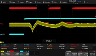
In my Oscilloscope waveform,
Red Channel is testing IC Pin-21 INT signal,
Blue Channel is testing Motor EN signal,
Yellow Channel is testing IC Pin-25 SYS (The Charger Output Voltage to System)